3.7V to 5V, 5.3V, and 6V Converter Circuit: The preferred voltage levels while working in most electronics projects lie between the value 5V to 6V. However, 3.6V-3.7V batteries are found abundantly in the market with a cheap price tag.
So, we presented an economic solution to generate commonly used operating voltages i.e. 5V, 5.3V, and 6V using these cheap and easily available 3.6V and 3.7V batteries. Using two-three batteries of 3.6V (3.6*2=7.2V) and 3.7V (3.7*2=7.4V) doesn’t provide the desired voltage level and thus this project was essential. This DC-to-DC converter project offers three different voltage levels; 6V, 5.3V, and 5V at the output terminal. You are free to use these output voltages at the same time for different purposes or separately at a time. This project is a boon to all digital and analog audio experiments and equipment that comprises portable components; audio amplifiers and MP3 players.
Description of 3.7V to 5V, 5.3V, and 6V Converter Circuit
The complete circuit diagram, of the voltage converter circuit, is given in fig.1. This low-cost project uses one switching regulator MC34063A (IC1), two 1N5819 Schottky diodes (D1 and D4), and two 1N4007 rectifier diodes (D2 and D3), two 5mm LEDs (LED1 and LED2) and some of the discrete components to develop the voltage converter circuit.
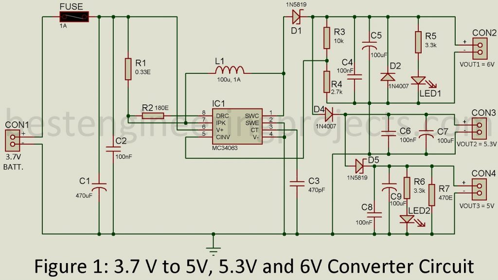
One terminal CON1 of the circuit is fed with the 3.7 DC voltage. The project operating voltage range lies in between the range of 3V to 40V. The input DC voltage reaches the IC1 and this regulator generates 6V DC output at the output terminal CON2. You can replace Schottky diodes 1N5819 with 1N5817, 1N5818, or 1N5819 series.
To produce the second output voltage from the converter circuit which is 5.3V, a single rectifier diode D3 is used as a step-down converter to generate 5.3V from 6V passed from IC1 and this voltage is available at the CON3 output terminal. Similarly, diode D4 takes the output from D3 and steps down the voltage level to 5V and this voltage level can be used through output port CON4. In this way, a combination of regulator and diodes is used to generate three different voltage values.
Working of the Circuit 3.7V to 5V, 5.3V, and 6V Converter Circuit
For the values of components used in this project, a total of 100mA current is generated at the output terminal. This value can be modified using different values of components in the project. Along with the desired voltage levels, the project also ejects a 15mV ripple voltage, and to reduce its effects in the circuit, we have included capacitor C3 and LC/RC filters in the circuit.
You don’t need to make further corrections in the project for this particular output, however, it is considered best to constantly monitor the input and output voltage levels along with the current and operating frequency level of IC1, and induction current of L1 for precise measurement.
To test the circuit, you can feed a 3.7V input voltage from a Li-ion battery. Three 1.2V(3*1.2V=3.6V) NiCd or NiMH batteries can also be used. Instead of this, you can also feed a regulated 3.7V as input to the circuit for testing the circuit.
There are certain points to be considered before practically implementing this project. In absence of load in the circuit, the output voltage varies with the value of resistor R7 (270-470 ohms) used in the circuit. Similarly, to ensure the normal functioning of the circuit, a load of a value larger than 10mA should be fixed at terminal CON4. The current sensitivity of the circuit is dependent on the value of resistor R1.
Check out other power supply circuit posted on bestengineeringprojects.com
- Adjustable Ripple-Regulated Power Supply Using 741
- Variable Switching Power Supply
- Universal Digital Power Supply Circuit
- Stabilized Power Supply With Short-Circuit Indication
- Short Proof Variable Power Supply
- Adjustable Bipolar Voltage Regulator Circuit Using LM337
- Self Switching-off Power Supply
- Dual Polarity 5v from 9v Battery
PARTS LIST OF 3.7V TO 5V, 5.3V, AND 6V CONVERTER CIRCUIT
| Resistors (all ¼-watt, ± 5% Carbon) |
| R1 = 0.33 Ω /0.47 Ω
R2 = 180 Ω R3 = 10 KΩ R4 = 2.7 KΩ R5, R6 = 3.3 KΩ R7 = 470 Ω |
| Capacitors |
| C1 = 470 µF, 16V (Electrolytic Capacitor)
C2, C4, C6, C8 = 100nF (Ceramic Disk) C3 = 470pF (Ceramic Disk) C5, C7, C9 = 100 µF, 16V (Electrolytic Capacitor) |
| Semiconductors |
| IC1 = MC34063A (DC-to-DC converter control circuit)
D1, D4 = 1N5819 (Schottky diode) D2, D3 = 1N4007 (Rectifier Diode) LED1, LED2 = 5mm LED |
| Miscellaneous |
| CON1 – CON4 = 2-pin terminal connector
F1 = 1A Fuse with holder L1 = 100µH, 1A inductor 3.7V Li-ion battery or 3×1.2V NiCd Batteries |