This Self Switching Off Power Supply Circuit switches itself off when no current is drawn by the load. When a load current flows, the potential difference across diode D6 is sufficient to cause diode D7 = and transistor T2 to conduct.
Transistor T1 is then switched on and the relay is energized. If you are new to relay drive circuits then you can watch this making video on How to make relay switching circuits. When the load current ceases, T2 switches off. The base current of T1 then charges capacitor C2 so that after a few seconds the relay is de-energized. The relay contacts switch to N/C and thus switch off the AC mains supply at the primary side of the transformer. The supply is switched on again by reconnecting the load and pressing switch SW1 momentarily.
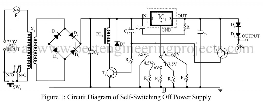
The output voltage of the power supply depends on the resistance between points A and B in the circuit. A wire link there results in an output voltage of about 3.5V. For each 100Ω increase, the output voltage will rise by about 1 V. This facilities variable output voltage with some resistor and a rotary switch.
The AC rating of the secondary transformer X1 must be about 1.5 times as high as the desired DC output current. The output current should not exceed 1-amp; if that magnitude of the current is drawn regularly, it is recommended to increase capacitor C1 to 1500 µF.
The delay in switch-off may be extended by increasing the value of capacitor C2. The heat sink of IC1 should be in accordance with the output current.
PARTS LIST OF SELF SWITCHING OFF POWER SUPPLY CIRCUIT
|
Resistors (all ¼-watt, ± 5% Carbon) |
|
R1 = 1 KΩ R2 = 4.7 KΩ R3 = 10 KΩ R4 = 100 Ω R5 = 270 Ω R6 = 390 Ω R7 = 560 Ω |
|
Capacitors |
|
C1 = 470 µF to 1500 µF, 25V C2 = 100 µF, 25V C3, C4 = 100 pF |
|
Semiconductors |
|
IC1 = LM7805 (T03 aluminum package rated for 1 A.) T1 = BC547B (General Purpose NPN Silicon Transistor) T2 = BC557B (General Purpose NPN Silicon Transistor) D1 – D7 = 1N4001 (Rectifier Diode) |
|
Miscellaneous |
|
X1 = 230V AC primary to 0 – 12V 1A secondary transformer RL1 = 12V, 100Ω relay F1 = fuse SW1 = Push to on switch SW2 = single pole 5 way rotary switch |
your work is very good