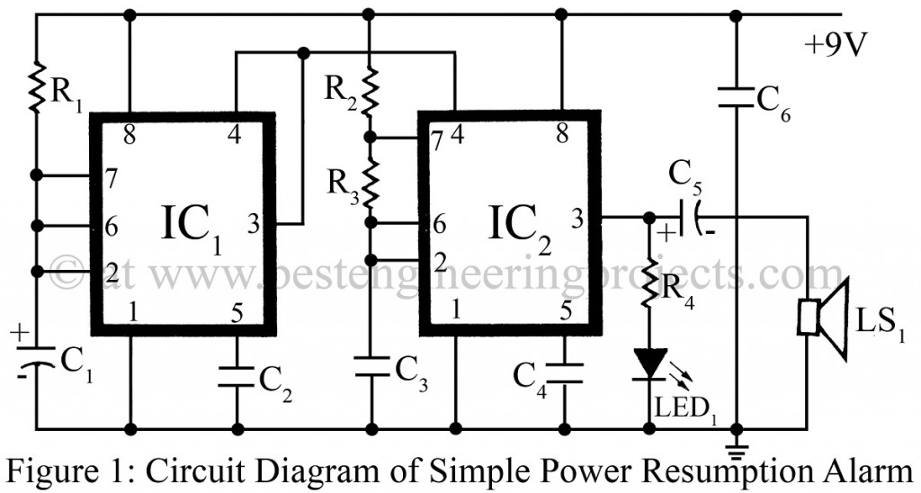
Once again the most popular timer IC NE555 proved that its applications are limited only to the user’s ingenuity. The circuit of the simple power resumption alarm shown here is straightforward, where IC1 is wired in a special kind of mode.
Circuit Description of Simple Power Supply Resumption Alarm
When the power supply resumes, pin 2 of IC1 is grounded through C1 and pin 3 goes high. This makes reset pin 4 go high for about 10 seconds. When the capacitor C1 charges to two-thirds of the supply voltage, the output of IC1 goes low, grounding the reset pin 4 and thus disabling the entire circuit.
The alarm circuit is wired around a second timer IC, IC2. Here it is used as an astable multivibrator, the frequency of which is about 1 kHz. This IC, IC2 is enabled when the output of IC1 goes high.
Check out other various different sound generators posted in bestengineeringprojects.com
- Grasshopper Sound Generator Circuit using 555 Timer IC
- Multi Sound Generator Circuit
- Wind Sound Generator Using IC 741
- Rain Sound Generator
Thus, the speaker produces an alarm for about 10 seconds. After 10 seconds, IC1 restores its stable state. Capacitor C1 discharges quickly through pin 7, and the circuit becomes ready for the next detection since pin 2 of IC1 is low. Thus, when power interrupts again an alarm is produced. The LED serves as an indicator.
PARTS LIST OF SIMPLE POWER RESUMPTION ALARM
|
Resistors (all ¼-watt, ± 5% Carbon) |
|
R1 = 1 MΩ R2 = 1 KΩ R3 = 68 KΩ R4 = 330 KΩ |
|
Capacitors |
|
C1 = 10 µF, 12V (Electrolytic Capacitor) C2, C3 = 0.01 µF (Ceramic Disc) C4, C6 = 0.1 µF (Ceramic Disc) C5 = 100 µF, 12V (Electrolytic Capacitor) |
|
Semiconductors |
|
IC1, IC2 = NE555 (Timer IC) LED |
|
Miscellaneous |
|
LS1 = 8Ω loudspeaker |

please tell me at least 3-4 real life applications of this circuit (simple power resumption alarm).