This project “Staircase Light Switch Circuit” may be used where it is necessary to control a single light or device by switches situated at different places. The control of a staircase light switch circuit is one of the applications of a light switch circuit. Staircase Light switch circuit can also be used to control an outdoor light using switches situated both inside and outside of the house.
Any number of switches may be connected to the light switch circuit. As the switches are wired in parallel, the wiring can be done using a 2-wire system. This circuit has simpler wiring as compared to a conventional electrical circuit.
An LED may also be added next to each switch to indicate whether the light is on or off. This feature can be useful when the light is far from the switch and cannot be seen easily. If LEDs are used for indication, another wire has to be used for connecting the switches to the circuit.
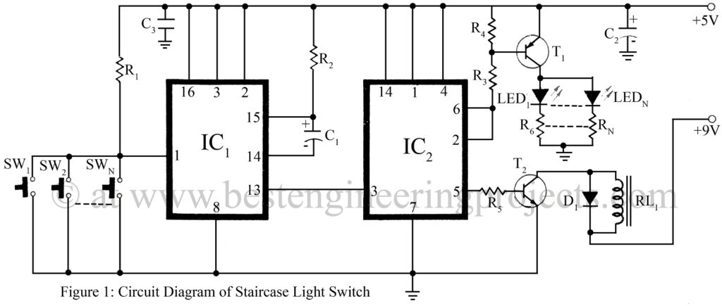
The light switch circuit is based on two low-power Schottky ICs. IC1 is a dual non-re-triggerable monostable multivibrator while IC2 contains two D-type flip-flops. IC1a is wired as a monostable multivibrator that supplies o 0.5-second pulse whenever any of the pushbuttons are pressed. These pulses clock the D-type flip-flop which divides by two. The first pulse will make the output of the flip-flop high while the next time the push button is pressed, the output will go low.
The output of the flip-flop is connected to a transistor which drives a relay. The relay controls the load which may be a light or any other electrical appliance. The relay contacts should be rated higher than the load current. A transistor controls the LEDs which are used for indication. If the LEDs are not required, they need not be included in the circuit.
Other switching circuits posted in bestengineeringprojects.com
- How to Make Relay Switch Circuit
- Light Sensor Switch Circuit using LDR and 741 IC
- Touch Switch Circuit using Transistor
- Clap Switch Circuit Using 555
- Staircase Switch Circuit
PARTS LIST OF STAIRCASE LIGHT SWITCH CIRCUIT
Resistors (all ¼-watt, ± 5% Carbon) |
|
R1 = 560 Ω R2, R3 = 10 KΩ R4 = 47 KΩ R5 = 1.5 KΩ R6 – RN = 470 Ω |
Capacitors |
|
C1 = 47 µF/6.3V C2 = 10 µF/16V C3 = 0.1 µF |
Semiconductors |
|
IC1 = 74LS221 (Dual Monostable Multivibrator Schmitt Trigger ic) IC2 = 74LS74 (Dual D-Type Flip-Flip IC) T1 = BC157 ( silicon PNP transistor) T2 = BC147 (NPN General Purpose Small-signal Driver Transistor) D1 = 1N4001 (General Purpose Rectifier Diode) LED1 – LEDN = different color LEDs |
Miscellaneous |
|
SW1 – SWN = Push to on switch RL1 = 6V, 200Ω Relay |