Today, I have come up with another simple but very applicable project ‘Touch Switch Circuit using Transistor’. With this simple project, you can modify your existing electrical/ electronic appliance with a modern touch facility.
A few days earlier I bought a reading lamp from one of the Chinese stores, the design of the Chinese product is quite impressive. The thing that motivates me to write this post is touch facilities i.e. you can on and off the lamp by simply touching the touch plate. The circuit posted here used two individual switches for ON and OFF.
Circuit Description of Touch Switch Circuit
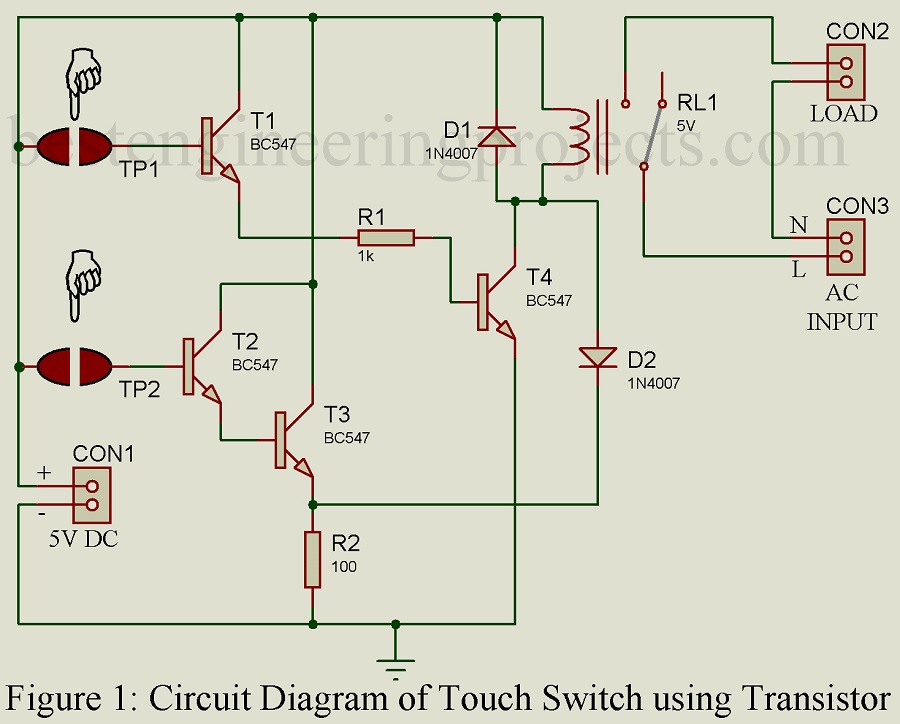
The circuit of the touch switch is shown in figure 1. This circuit is designed using four general-purpose low-power NPN transistors. Transistors T2 and T3 are configured in the Darlington pair. As the input resistance of the circuit is high and also this type of circuit requires high current gain thus we used the Darlington pair transistor.
A transistor may serve various functions but basically, it is used to amplify an electrical signal. Here, also we are using a transistor for amplification. Darlington pair of the transistor is a combined unit of two emitter follower circuits that are connected in cascade and enclosed as one package.
The transistor is biased for active region operation. To increase the current gain of the output-state transistors, and thus reduce the required base current drive, the Darlington configuration is frequently used to replace the NPN transistor. The Darlington configuration is equivalent to a single NPN transistor having  , but almost twice the value of base voltage.
Working of the Touch Switch Circuit
When touch plate TP1 is touched, the base voltage Vbe of transistor T1 and T2 becomes high which energized the relay RL1 as a result electrical or Electronics appliance is activated. Similarly, when touch plate TP2 is touched Darling pair (transistor T2 and T3) becomes high as a result voltage is developed across resistor R2. This voltage developed across resistor R2 de-energized the relay RL1 and the further electrical or electronic appliances are de-activated.
The touch plate must be made from copper, you can either use a copper plate or copper wire.
You can also check various touch switch circuits.
- Simple Touch using two transistor
- Touch Switch cum heat Operated Switch
- Clap switch cum Touch switch
- Touch Dimmer Circuit
PARTS LIST OF TOUCH SWITCH CIRCUIT
| Resistors (all ¼-watt, ± 5% Carbon) |
| R1 = 1 KΩ
R2 = 100 Ω |
| Semiconductors |
| T1 – T4 = BC547 (General Purpose Low Power NPN Transistor)
D1, D2 = 1N4007 (General Purpose Rectifier Diode) |
| Miscellaneous |
| RL1 = 5V, 1CO Relay
TP1, TP2 = Touch Plate (Copperplate or Wire) CON1, CON2, CON3 = Two Pin Connector |
Where is the pcd diagram
Pcb diagram **