Security is a major concern in today’s world. Criminal minded people, who find robbing as a better way of earning, are increasing more day by day. Previously, we had posted Accident Detection and alert system using arduino which also works on same logic.
Automobiles are more vulnerable to theft since there are tons of vehicles left unused and the fact that each part of the system provides quite a good amount of money makes it more fascinating. Among many other automobiles, cars top the list of being stolen globally. Thieves find cars as easy target also because they offer less security features. People introduced solutions to boost security but they were not able to put an end to this growing issue.
Components Required for Car Lock System using Arduino and GSM
Arduino UNO x1
SIM900 GSM Module x 1
BC337 Transistor x 1
1N4007 Diode x 1
7809 Voltage regulator IC x 1
10k Resistor x 1
1000uF,20V Electrolytic Capacitor x 3
4.7uF, 20V Electrolytic Capacitor x 1
12V DPDT Relay x 2
1A Fuse x 1
Push-to-on Switch x 1
More automotive circuit posted in bestengineeringprojects.com
- Automobile Brake Failure Indicator
- Arduino Based Car Reverse Alarm
- Automatic wiper for Automobile using Arduino and Rainsensor
- Car (Automobile) Battery Maintaining Circuit
- Beeper for Automobile Flasher Using 555
- Car Reverse Horn Circuit
Circuit Description Car Lock System using Arduino and GSM
The project encompasses GSM modem (SIM 800/900) as the core component of the project along with a Arduino board. The project offers security to ignition system of the car which is more vulnerable to be hacked. The ignition system and central lock of the car can be enabled or disabled by the relay circuit interfaced to the arduino board. We also require a valid SIM card with activated sms plan to transfer information from this project at reduced cost because of the SMS offers distributed by the network provider.
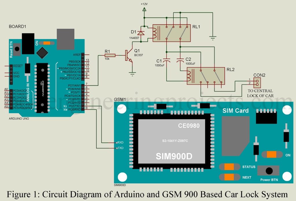
Looking at the complete circuit diagram of the GSM car central locking system based on Arduino:
The overall circuit is much easier to understand and implement. Initially, establish the link between GSM modem and the arduino uno board by connecting Tx and Rx pin of the modem to Rx and Tx pin of the Arduino. Then establish the ground to ground connection between two devices.
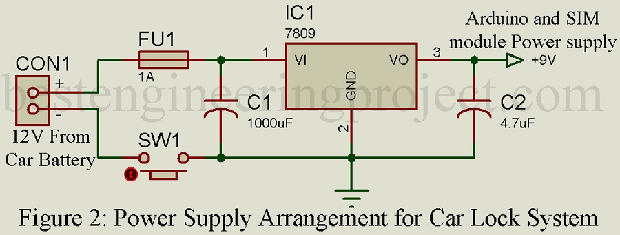
Concerning the power supply required for the project, we must be very careful. Any irregular voltage supply may damage the modules used, which is the case if we use battery as the power source since it is prone to vary while ignition and charging. So, we opted for a 9V regulator 7809 that supplies a constant voltage to the GSM modem and arduino board.
Pin no. 7 of the Arduino board is assigned as the output terminal that supplies input to the central lock and ignition lock mechanism. Diodes included in the circuit prevent failure because of high voltage spike from relay due to back EMF. So as to avoid possibilities of short circuit in the project, a fuse must be included at the input terminal. Switch is placed inside the bonnet which can be used to turn off the circuit in case if the car won’t be used for over a week to save battery.
When the switch is off, the central and ignition lock of the car is activated and hence the car is safe.
Software Code for Car Lock System using Arduino and GSM:
The software code for Car Lock System using arduino is written in arduino programming language and compiled is arduino IDE. You can download the complete code from the below link and use it in your system.
CLICK HERE TO DOWNLOAD SOFTWARE CODE
Here is how the SMS plan works:
- When any information is passed to the GSM modem, an SMS is forwarded to the car owner’s phone number revealing about the current status of the lock.
- The state of central and ignition lock can only be toggled with the correct password.
The result is from the tested prototype.
- When a specified information is sent to the SIM card number inserted in the GSM modem, it resends an acknowledgement SMS regarding the current status of the lock to car owner’s phone number.
- In above case, if correct password (i.e. /qwerty/ for this project) is supplied to the GSM modem, it will unlock the lock and also sends an acknowledgement.
- To lock the lock, send the same correct password again.
Points to be considered while working with this project:
NOTE 1: The password should be surrounded by ‘/’ sign.
NOTE 2: Wait for a while when the circuit is turned on. It should respond with a SMS ; “Your car is ready to accept SMS command” to car owner’s cellphone number. Then you can proceed by sending SMS commands.