Almost 40% of accidents occur because of brake failure issues. With early identification of this condition, we can reduce the accident rate. The project ‘Automobile Brake Failure Indicator’ is the solution to this global issue.
You might be wondering how this project is responsible to lower the accident rate. Well, this indicator circuit keeps an eye on the condition of the brake at regular intervals and provides an audio-visual indication of the situation.
The project includes two LEDs and a piezo buzzer as indicators. Under normal circumstances when the brake is applied, the green LED blinks and the piezo buzzer beeps for a second. However, during brake failure, the red LED glows and the buzzer doesn’t beep).
The project Automobile Brake Failure Indicator is limited to those vehicles with negative grounding, else this project doesn’t work. Providing information about the brake switch failure is another feature of this project.
More automotive circuits posted in bestengineeringprojects.com
- Car Lock System using Arduino and GSM
- Arduino Based Car Reverse Alarm
- Automatic wiper for Automobiles using Arduino and Rainsensor
- Car (Automobile) Battery Maintaining Circuit
- Beeper for Automobile Flasher Using 555
- Car Reverse Horn Circuit
Circuit Description and Working of Automobile Brake Failure Indicator
The circuit diagram of the Automobile Brake Failure Indicator is shown in figure 1. The mechanism on basis of which this automatic brake failure indicator project is developed is explained in detail here. Actually, most vehicles have hydraulic brake systems. So as to control the rear brake lamps, a brake switch is fixed right above the brake cylinder.
The brake switch being fluid-operated doesn’t function when the fluid pressure drops down due to leakage. Keeping this property in mind, the project is developed such that it monitors the brake switch constantly. The drop-in fluid pressure is only noticeable when the fluid leakage is high enough to cause a heavy drop in the pressure level of the brake. The project informs every single time the brake is applied.

Talking about the circuit elements, it uses an op-amp IC CA3140 (IC2) as a voltage comparator and a timer NE555 (IC3) in a monostable configuration to sound an alarm. The voltage level across the brake switch is monitored by the IC2 to check the pressure level. Half amount of the supply voltage is fed to the pin3 (non-inverting) of IC2 through potential divider resistors R3 and R4, each of 10 kilo-ohms. Similarly, the brake switch is linked to the inverting input pin 2 of IC2 via diode D1, IC 7812 (IC1), and resistor R2. When the brake is applied, pin2 receives high voltage.
Initially, the output of IC2 is high and the red LED is on. The output from IC2 activates the IC3 once it is fed as input through coupling capacitor C2 to trigger pin 2. To maintain the input stability of IC2, resistor R1 is included. A combined combination of IC1 along with capacitor C1 offers a ripple-free regulated supply to the inverting input of IC2.
IC3 provides an output pulse of one second and it is wired as such; a monostable. Resistor R7 and capacitor C4 serve as timing elements and they contribute to high output for a second to operate the buzzer and green LED. Initially, the buzzer and green LED are off as the trigger pin of IC3 is high due to resistor R6.
Once the brake switch is closed, IC2 receives high voltage via pin2 and the IC output falls low to turn the red LED off. IC3 gets triggered by the low output of IC2 which passes through C2. Finally, the buzzer beeps and the green LED turns on to indicate that the brake is working smoothly. However, in case of failure, even after the brake is applied, the red LED keeps on glowing and the buzzer doesn’t sound.
Designing of Automobile Brake Failure Indicator
It is easy to design the circuit of an Automobile Brake Failure Indicator. A general-purpose PCB or any perforated board can be used as a platform to develop the complete circuit. As illustrated in the figure, the brake switch is connected to point A. The power supply required for the circuit can be easily obtained from the vehicle’s battery.
For the smooth functioning of the project Automobile Brake Failure Indicator, a well-regulated supply is a must. Else, false triggering may occur as the battery charges itself from the dynamo. To ensure smooth operation, IC4, C6, and C7 collectively provide a regulated power supply; of 12V to the circuit. It is to be noted that the power supply should be taken from the ignition switch and the circuit ground should be clamped to the vehicle’s body. You can also replace green and red LEDs with a bicolor LED to simplify the installation process.
PCB Diagram
PCB diagram is designed using Proteus 8.1. The actual side solder side and component side are shown in the figure below. Download the PCB diagram from the link given below.
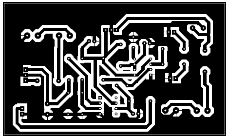
Figure 2: Solder Side PCB of Automobile Brake Failure Indicator
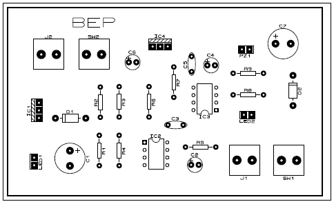
Figure 3: component side PCB of Automobile Brake Failure Indicator
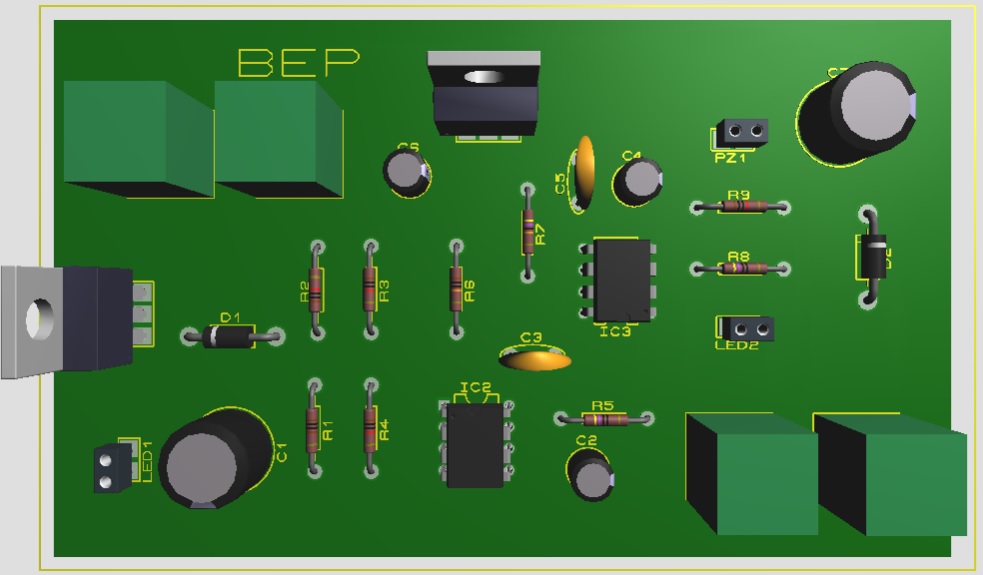
Figure 4: 3D view of Automobile Brake Failure Indicator
PARTS LIST OF AUTOMOBILE BRAKE FAILURE INDICATOR
| Resistors (all ¼-watt, ± 5% Carbon) |
| R1 = 1KΩ
R2 – R4, R9 = 10 KΩ R5, R8 = 470Ω R6 = 100 KΩ R7 = 470 KΩ |
| Capacitors |
| C1, C7 = 1000 µF/25V (Electrolytic Capacitor)
C2 = 0.02 µF (Ceramic Disc) C3, C4 = 10 µF/25V (Electrolytic Capacitor) C5 = 0.01 µF (Ceramic Disc) C6 = 100 µF/25V (Electrolytic Capacitor) |
| Semiconductors |
| IC1, IC4 = LM7812 (12V Series Voltage Regulator IC)
IC2 = CA3140 (Op-Amp IC) IC3 = LM555 (Timer IC) D1, D2 = 1N4007 (Rectifier Diode) LED1 = 5mm Red Color LED LED2 = 5mm Green Color LED |
| Miscellaneous |
| SW1 = Ignition Switch
SW2 = Brake Switch PZ1 = Piezo Buzzer |