Here is a simple circuit built around very common electronics components easily available in the local market which is used to protect car (automobile) batteries from deep discharge and also protect from getting damaged.
Let’s get some facts about automobile batteries. We all know that battery itself has some self-discharge rate which depends upon battery capacity and the materials used to make it. Various reasons discharge a battery like an electrical installation in a car. When we do not use our automobile for a longer period the battery becomes fully discharged or also sometimes it gets damaged too.
To overcome this problem, we have discharged a circuit that let the battery remains always charged.
More automotive circuits are posted on bestengineeringprojects.com
- Automobile Brake Failure Indicator
- Car Lock System using Arduino and GSM
- Arduino Based Car Reverse Alarm
- Automatic wiper for Automobile using Arduino and Rain sensor
- Beeper for Automobile Flasher Using 555
- Car Reverse Horn Circuit
Circuit Description of Car (Automobile) Battery Maintaining Circuit
The circuit of the Car (Automobile) Battery Maintaining Circuit is shown in figure 1. This circuit is a power supply unit. The main supply is given to one input of switch SW1 as shown in the circuit diagram which is further stepped down to 21V using stepped-down transformer X1. This voltage is changed to pulsating dc using a bridge rectifier comprising diodes D1 through D4.
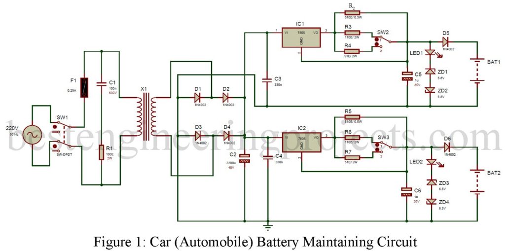
From the circuit shown above, we conclude that there are two channels, each channel contains a voltage regulator IC 7805 (IC1 and IC2). The interesting fact is that here we are using these IC (7805) as a current generator rather than 5V fixed voltage regulators. Resistor R2 is used to maintain a minimum output current of 10mA for battery 1 similarly R5 does the same job for battery 2.
The maximum output current of about 50mA or 100mA can be selected using switch SW2 for channel 1 and switch SW3 for channel 2. At position 1 of switch SW2/SW3, the maximum output will be 50mA similarly at position 2 of switch SW2/SW3 the output will be 100mA.
LED1 with Zener diode ZD1 and ZD2 is used to limit the maximum output voltage to 15.5V for channel 1. Similarly, this job is done by LED2 with zener diode ZD3 a ZD4 for channel 2.
To prevent the discharging of the battery, we used diode D5 for channel 1 and Diode D6 for channel 2. This is done because the normal PN diode does not connect in reverse bias. Hence no voltage flow through it.
Construction of Car (Automobile) Battery Maintaining Circuit:-
Actual Size, Solder-Side PCB design of Car (Automobile) Battery Maintaining Circuit is shown in figure 2. Similarly, the components side is shown in figure 3. The complete circuit is kept in a small enclosure box and its input and output can be taken from the front and back panels respectively.
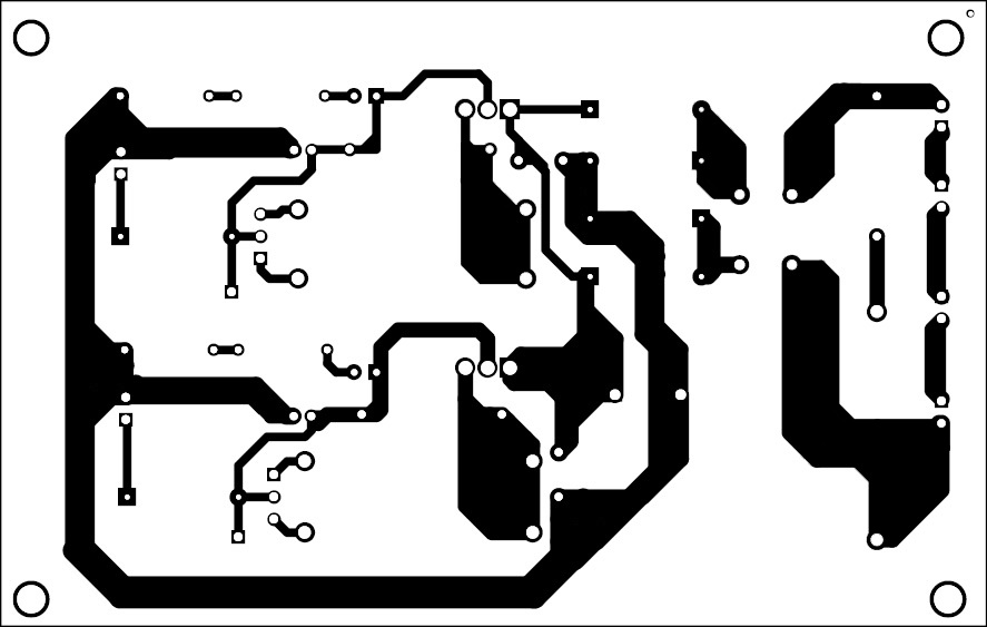
Figure 2: Solder side PCB design of Car (Automobile) Battery Maintaining Circuit
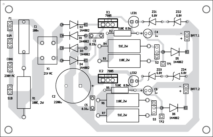
Figure 3: Component side PCB design of Car (Automobile) Battery Maintaining Circuit
BEP Note: The two ICs (IC1 and IC2) most mount in the individual heat sinks. and its ground pin (pin 2) should be connected to the heat sink.
Click Here to download PCB Design
PARTS LIST CAR (AUTOMOBILE) BATTERY MAINTAINING CIRCUIT
| Resistor (all ¼-watt, ± 5% Carbon) |
| R1 = 100Ω, 2W
R2, R5 = 510Ω, 0.5W R3, R6 = 110Ω, 2W R4, R7 = 51Ω 2W |
| Capacitors |
| C1 = 100nF, 630V (Polyster Capacitor)
C2 = 2200 µF, 40V (Electrolytic Capacitor) C3, C4 = 330nF (Ceramic disc) C5 C6 = 1 µF, 35V (Electrolytic Capacitor) |
| Semiconductors |
| IC1, IC2 = 7805, 5V voltage regulator
D1 – D6 = 1N4002 rectifier diode ZD1 – ZD4 = 6.8V zener diode LED1, LED2 = 5mm any color LED |
| Miscellaneous |
| X1 = 230V AC primary to 21V, 200mA secondary transformer
SW1 = DPDT Switch SW2, SW3 = SPDT Switch F1 = 0.25A fuse with holder BATT1, BATT2 = 12V battery |