Arduino Based Car Reverse Alarm: We prefer to stay alert than to face the consequences as the result of our ignorance. They say, ‘Prevention is better than cure’ and this project; “Car Reversing alarm” serves us the right purpose.
It is designed such that the device sounds an alarm as individual reverses a car for parking in a specific location and it detects any sort of obstacles there, that may create unwanted troubles. The device outputs audible sound wave as well as a visual indication to make the individual aware of the situation. The project is built around the AVR microcontroller and ultrasonic module.
More automotive circuit posted in bestengineeringprojects.com
- Automobile Brake Failure Indicator
- Car Lock System using Arduino and GSM
- Automatic wiper for Automobile using Arduino and Rainsensor
- Car (Automobile) Battery Maintaining Circuit
- Beeper for Automobile Flasher Using 555
- Car Reverse Horn Circuit
Circuit and Working of Arduino Based Car Reverse Alarm
The simple arduino based layout of the project is given in figure 1. As stated earlier, the ATmega328 AVR microcontroller (IC1) is the heart of the circuit. It is accompanied by other components like a 5V regulator (IC2), ultrasonic module HC-SR04, piezo buzzer (PZ1) etc.
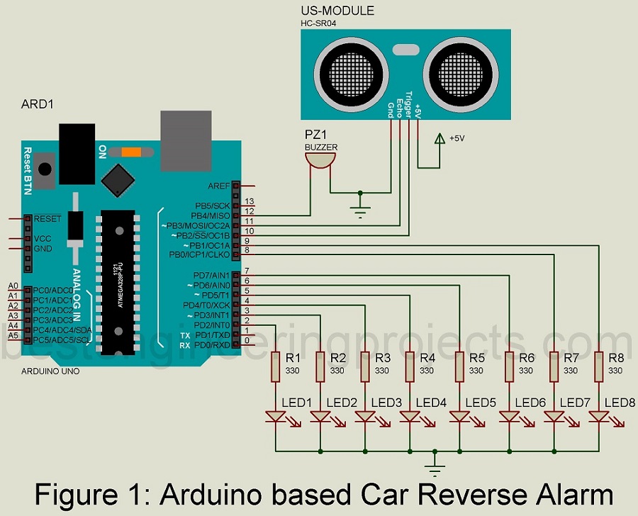
The ultrasonic module is interfaced with the microcontroller by connecting its trigger and echo pins with pins 16 and 17 of IC1. A piezo buzzer is fixed at pin 18. For this project and components used, the preset limit of the distance in between the rear part of the car and the obstacle is fixed at 25 cm, and that is when the buzzer starts beeping to alert the user.
Furthermore, a LED arrangement provides visual details of the distance between the car and the obstacle. Eight LEDs (LED1-LED8) are connected across pins 4 through 6 and 11 through 15 of IC1.
The clock frequency required for the IC1 is supplied by the 16MHz crystal oscillator connected across pins 9 and 10 of IC1. Resistor R10 and a capacitor C5 are combined together to supply the power-on reset for the circuit. So as to reset the microcontroller when required, a switch S1 is included.
Ultrasonic transceiver HC-SR04.
Ultrasonic transceiver HC-SR04 module is used to locate the distance of the obstacle from the car and it uses sonar for that purpose. The module offers precise range detection in between the range of 2 cm-400 cm. The fact that it provides accurate and stable readings make it more suitable for use.
When Pin 2 (TRI) of the module receives ‘high’ pulse for a period more than 10µs, only then the distance can be calculated. This verifies the presence of obstacle and triggers the module to send eight cycles of ultrasonic burst at 40kHz and then the device waits till the reflected ultrasonic signal is received. Once that happens, the echo pin (pin 3) of the module is set high. The waiting period for reflected pulse is completely dependent upon the distance at which the obstacle is located. When the waiting time is detected, we can calculate the distance by using the formula listed below:
Distance (in centimeters) = T/58,
where T = Width of pulse at Echo pin in micro seconds
Power supply for Arduino Based Car Reverse Alarm
The circuit is powered by converting a 12V DC supply from car’s battery or external DC source into a 5V supply with the help of 7805 regulator. When the power is available, LED9 is turned on.
Software Code for Arduino Based Car Reverse Alarm
The project uses Arduino programming language and an Arduino IDE is used to compile and burn the code into the microcontroller. In the code, the maximum distance at which an obstacle can be located is set at 200cm for the smooth operation of the project.
Click Here to download software
Components used in Arduino based Car Reverse Alarm
R1 – R8 = 330 Ω
LED1 – LED8 = 5mm Any color LED
Arduino Uno Board
HC-SR04 Ultrasonic Sensor
Buzzer