The circuit posted here is of sound level meter using arduino uno board, microphone, Amplifier section and LCD module. The basic function of this project is to measure the intensity of sound and display the result in LCD module. This project can be used in any small closed room like living room, class room etc. The result of sound level is display in LCD module in decibel unit. Here, we had used normal microphone despite of any expensive microphone or sensor. We had already built a sound level meter using amplifier and LED bar.
Description of Sound Level Meter Circuit using Arduino
The circuit of sound level meter is shown in figure 1. The main or controlling part of the system is arduino UNO board which is basically a development a development board consisting ATmega 328 microcontroller.
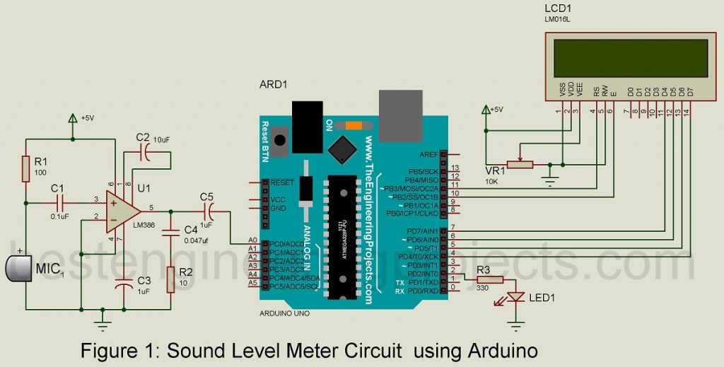
Now, talking about microphone and amplifier section. Here in our prototype we had used a condenser microphone. This microphone defect sound signal and convert it into corresponding electrical signal. Sensitivity of microphone is determined by resistor R4. The electrical signal from microphone is very weak and need amplification. This job (amplification) is done by an op-amp LM386. IC LM386 is low voltage battery powered amplifier, designed for application where low power is main concern. The amplifier section is designed here for 200 gains and output is biased to ½ of supply voltage.
Capacitor C1 is coupling capacitor which filter out DC noise of microphone if any. Similarly, capacitor C5 is also used for DC filter because sometime while amplification DC noise may be added. The amplified output is given to analog pin A0 of arduino UNO board. As we know that an ADC analog to digital converter is connected to analog pin of arduino UNO board. Thus, we get corresponding digital value of sound signal picked by microphone. This digital value is converted to dB using Regression method.
|
Table 1: ADC Value VS dB |
|
| ADC | dB |
| 460 | 44 |
| 480 | 47 |
| 500 | 59 |
| 508 | 60 |
| 550 | 61 |
| 600 | 63 |
| 613 | 65 |
| 700 | 70 |
| 859 | 78 |
As the value of dB is not linear to ADC value. Thus, we had used straight method where we had managed a table which shows corresponding dB value of ADC. If we plot a graph from the value given in table is looks like below.
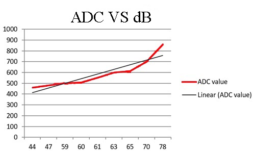
Now, apply linear regression method to find the possible straight line. From the straight line we can find the equation which can be used in the code for calculating the value of dB from ADC.
The equation we had derived from straight line looks like below;

Therefore, 
We had used this equation for calculation dB from ADC value.
Software Code for Sound Level Meter Circuit using Arduino:
The software code for sound level meter is written in arduino programming language and compiled and burned using arduino IDE. You can directly download the code and use in your project.
CLICK HERE TO DOWNLOAD SOFTWARE CODE
PARTS LIST OF SOUND LEVEL METER USING ARDUINO
| Resistor (all ¼-watt, ± 5% Carbon) |
| R1 = 100Ω
R2 = 10 Ω R3 = 330 Ω VR1 = 10 KΩ |
| Capacitors |
| C1 = 0.1µF (Ceramic Disc)
C2 = 10 µF/16V (Electrolytic Capacitor) C3, C5 = 1µF/16V (Electrolytic Capacitor) C4 = 0.047µF (Ceramic Disc) |
| Semiconductors |
| U1 = LM386 (Low Voltage Audio Power Amplifier)
LED1 = 5mm, any color LED ARDUINO UNO BOARD |
| Miscellaneous |
| 16×2 Alphanumeric LCD module
MIC1 = Condenser Microphone |