Previously we presented ‘Arduino Based RF-controlled Robot’. This project ‘PIC16F877A Based Dual Mode Robot’ includes slight modifications to that project. This Robot has inbuilt features to identify and avoid obstacles on its way and can be easily controlled with the help of RF-based remote control.
The project can be used as a base to build up projects like automatic vacuum cleaners along with some modifications. The best part in that context is that artificial intelligence cleans the floor on its own and we can guide the robot to clean areas using RF remote as well. That sounds interesting, right?
Let’s move on to the design part.
Other Robotic projects posted on bestengineeringprojects.com
- Arduino based Bluetooth Controlled Car
- Arduino and RF Controlled Robot
- Arduino Gesture Controlled Robot
Circuit Description of PIC16F877A Based Dual-Mode Robot
The project uses a PIC microcontroller as the main component. As we command the robot to operate using a remote controller, it passes the corresponding code through an RF transmitter. The signal is received and then decoded for execution at the receiver side. There is a unit; MCU which makes the comparison and drives the motor accordingly. Special detectors are attached to the circuit for obstacle identification and to inform the microcontroller.
The details of remote control and robot construction are provided in Figures 1 and 2 respectively.
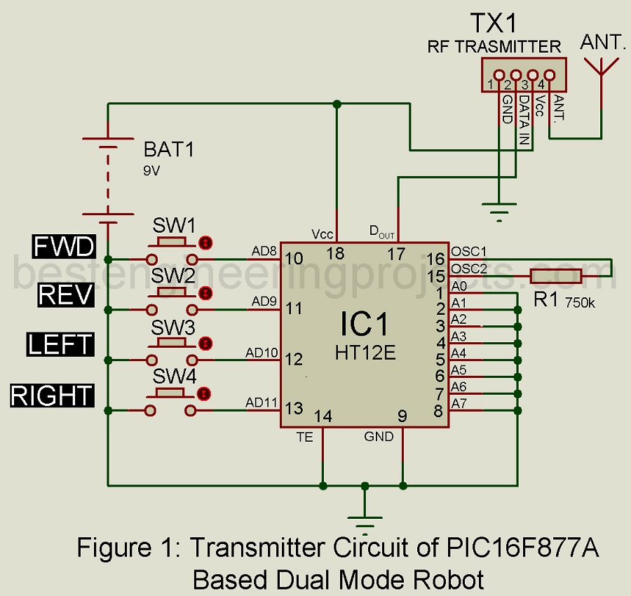
Transmitter Circuit for PIC16F877A Based Dual-Mode Robot
The remote-control section of this project is identical to the transmitter circuit of our previous project; ‘Arduino-based RF-controlled robot’. For more information, please open this link: Arduino and RF Controlled Robot.
Receiver Circuit for PIC16F877A Based Dual-Mode Robot
RF receiver module (RX1), decoder HT12D (IC2), microcontroller PIC16F877A (IC3), operational amplifier LM324 (IC5), motor driver L293D (IC6), regulator 7805 (IC4), and a few discrete components collectively form the robot. Once the data transmitted by the remote is detected, the RF receiver module fetches the signal and IC2 is responsible for decoding the signal.
The data is then passed onto microcontroller IC3 through pins RA0 to RA3. The encoder and decoder are shorted to the ground and identical addresses are selected. Pins RD0-RD3 of IC3 are connected to pins IN1-IN4 of IC6 to supply output from IC3 to drive motors M1 and M2 through IC6. To ensure output, enable pins EN1; pin 1, and EN2; pin 9 are maintained at high levels throughout the project.
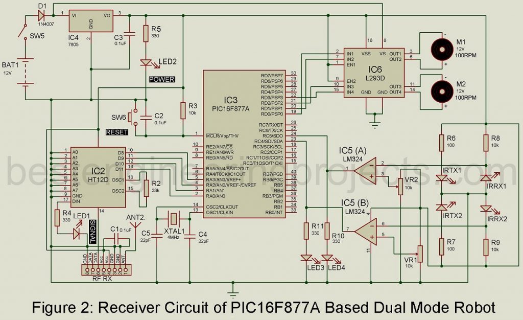
For power supply, a 12V battery is attached to motor driver IC6 through pin 8. Another IC; IC4 provides a regulated 5 supply for the circuit. As obstacle detectors, two IR transmitter-receiver pairs are included in the circuit. The reference voltage of two operational amplifiers in IC5 is fixed by Presets VR1 and VR2.
As the device approaches any obstacle on its way, the IR beam is reflected from the obstacle. The outputs of operational amplifiers go high as the reference voltage exceeds the input voltage at the inverting pins. This situation is depicted by the glowing LED3 and LED4. Pins RC5 and RC4 of IC3 are connected to output pins 1 and 7 of IC5. Then the microcontroller operates according to the data received from the transmitter section and obstacle detectors.
Working on the Dual Mode Robot
The construction of the robot is easy and its working mechanism is much simpler. Initially, the robot is in manual mode, i.e. it should be controlled with a remote. A remote comprises a set of buttons designed for each particular direction. The robot stops moving ahead as it confronts any obstacles. It can move in other remaining directions.
To activate the automatic mode, switch S1 and S2 must be pressed simultaneously. In this mode, the robot moves in the forward direction and when it confronts any obstacles, it stops. And, then it steps back and turns 90 degrees to the right and continues moving in the forwarding direction, and turns left. Once it gets rid of that obstacle, it continues moving in a forwarding direction.
The automatic mode can be deactivated by pressing switches S3 and S4 simultaneously. This pattern can be altered as per our requirement.
Software of Dual Mode Robot
To make this project simpler, the source code is written in ‘C’ language. Later, using MPLAB IDE, the code is compiled. Since Windows is the common OS, this program is designed to run on this platform. The microcontroller uses the ‘pic_rf.c’ program. The fact that the program incorporates elaborated simple comments, makes it much easier to understand. The MPLAB compiler develops a hex code using the source file; ‘pic_rf.c’. The program loader is used to burn the hex code into the microcontroller.
Click Here to Download Software
Construction and Testing of PIC16F877A Based Dual-Mode Robot
Figure 3 illustrates the PCB layout of the entire remote circuit and the component layout is presented in figure 4. Figure 5 provides the PCB for the robot along with its component layout in Fig. 6. Connectors available on both PCBs are useful to interface motors, RF modules, and power supplies in the circuit.
Click Here to Download PCB Diagram
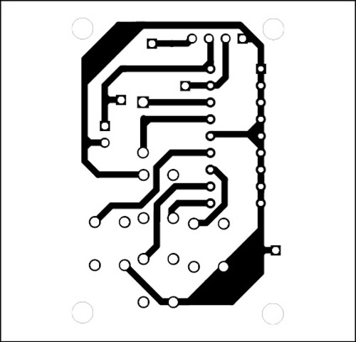
Figure 3: Solder Side PCB Diagram of Transmitter Circuit
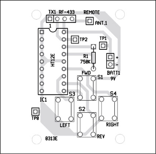
Figure 4: Component Side PCB Diagram Transmitter Circuit
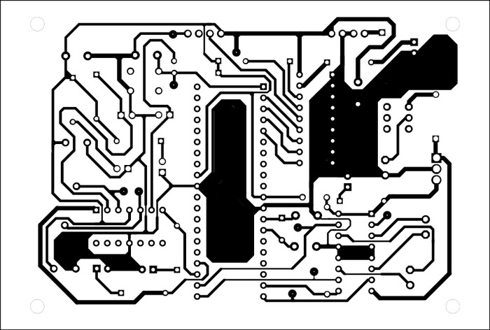
Figure 5: Solder Side PCB Diagram of Receiver Circuit
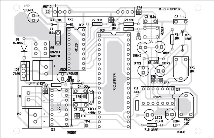
Figure 6: Component Side PCB Diagram of Receiver Circuit
PARTS LIST OF PIC16F877A BASED DUAL MODE ROBOT
| Resistors (all ¼-watt, ± 5% Carbon) |
| R1 = 750 KΩ
R2 = 33 KΩ R3, R8, R9 = 10 KΩ R4, R5, R10, R11 = 330 Ω R6, R7 = 100 Ω VR1, VR2 = 10 KΩ Preset |
| Capacitors |
| C1, C2, C3 = 0.1 µF (Ceramic Disc)
C4, C5 = 22 pF (Ceramic Disc) |
| Semiconductors |
| IC1 = HT12E (Encoder IC)
IC2 = HT12D (Decoder IC) IC3 = PIC16F877A (Microcontroller) IC4 = 7805 (5V, Series Voltage Regulator IC) IC5 = LM324 (Operational Amplifier IC) IC6 = L293D (Motor Driver IC) |
| Miscellaneous |
| SW1 – SW4, SW6 = Push-to-on Tactile Switch
SW5 = On/off Switch M1, M2 = 12V, 100-RPM Geared Motor BATT.1 = 9V Battery (PP3) BATT.2 = 12V, 4.5Ah Battery XTAL1 = 4MHz Crystal |