Arduino and RF Controlled Robot
‘ROBOT’, as you know were introduced much earlier in the fifties. People could not afford those massive devices because of the cost they were tagged with. But now, to make it available to common people as well, our team developed a robot that is based on a simple platform like Arduino. Due to the fact that it uses RF remote control, using this robot is much easier. The omnidirectional robot works smoothly within a range of up to 100 meters. Adding more to its benefit, it doesn’t take much time to construct this device.
Circuit Description of Arduino and RF Controlled Robot
Since the project incorporates RF remote control, there are two sections of this project: (a) transmitter (b) receiver, and motor driver. The details of these two sections are portrayed in fig 1 and fig 2 respectively. The first portion; the transmitter circuit comprises encoder IC HT12E (IC1), 433MHz RF transmitter module (TX1), and some discrete components. Other elements like Arduino UNO board (BOARD1), decoder IC HT12D (IC2), 433MHz RF receiver module (RX1), motor driver IC L293D (IC3), regulator IC 7805 (IC4), and discrete components build up the receiver circuit.
Arduino UNO board
The project is centered around Arduino uno. The fact that Arduino is an open-source device, it is flexible and much easier to use. This platform fits best for anyone who shows a keen interest in creative projects of interactive innovations.
Remote control
This is the best part of the entire project. For controlling the robot remotely, Holteks’ encoder-decoder pair (HT12E and HT12D) together with a 433MHz transmitter-receiver pair is used.
The Holteks pair are in fact CMOS ICs consisting of working voltage ranging from 2.4V to 12V. The two ICs come with eight addresses and four address/data lines respectively. As soon the TE pin; the transmit-enable pin is low, the data set on these twelve lines (eight addresses and four address/data lines) are serially transmitted and received at the DOUT pin.
After four successive attempts, all data are transmitted. The lengths of positive pulses of ‘1’ and ‘0’ vary in width to help with the identification issues. The pulse width of ‘0’ is two times that of the pulse width for ‘1’.In accordance with the resistor value between OSC1 and OSC2 pins, the corresponding frequency of these pulses falls in the range of 1.5 to 7 kHz.
In the Holteks’ pair, the decoder; HT12D has an internal oscillation frequency 50 times the oscillation frequency of encoder HT12E. Din pin in decoder collects input serially from the encoder. Matching of received data with the levels on A0 through A7 pins for four successive attempts verify the input and only then does valid transmission pin (VT) go high. Similarly, pin D8-D11 on HT12D reflects the data present on pins AD8 through AD11 of the HT12E. It can be concluded that the device performs as a receiver of 4-bit data (16 possible codes) along with 8-bit addressing (256 possible channels).
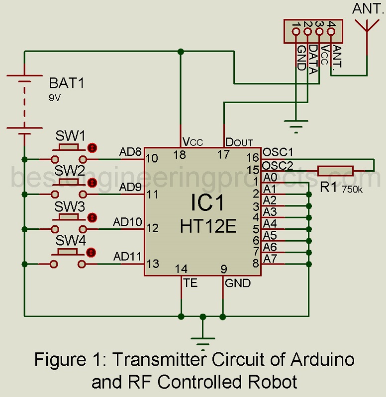
Transmitter circuit
The connection of switches and encoder pins is established on basis of this table:
| Switches | Pins of encoder HT12E | Purpose |
| S1 | AD8 | Forward motion |
| S2 | AD9 | Reverse motion |
| S3 | AD10 | Left motion |
| S4 | AD11 | Right motion |
Resistor R1 controls the transmitter frequency as it is adjusted in between the oscillator pins 15 and 16.
The TE pin of encoder HT12E is grounded to make it permanently enabled for transmission. For instance, let’s say switch S1 is on, then that particular data transmits serially from DOUT pin through the RF ASK transmitter module. A 9V battery is used as the power source to supply power to the circuit.
Receiver and Motor Driver Circuit
In the project, we assume that address pins on the encoder and the decoder are identical. When any switches(S1-S4) on the transmitter circuit are closed, the corresponding data pin of the decoder falls low. Then the data outputs obtained from pins D8 through D11 of the decoder are fed to pins 2 through 5 of the Arduino UNO board. Doing so, logic outputs are obtained from pins 8 through 11 of the Arduino UNO board.
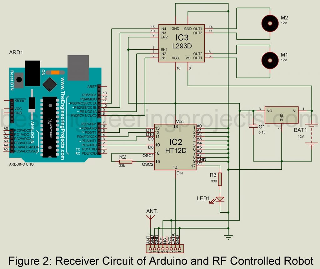
Now, so as to drive both the motors M1 and M2 these Arduino outputs are passed as inputs to IN1 through IN4 of L293D (IC3) to as shown in Fig. 3. OUT1 and OUT2, OUT3 and OUT4 drive motors M1 and M2 respectively. To get permanently enabled output at the end, enable pins EN1 (pin 1) and EN2 (pin 9) to be connected to Vcc. Regulator 7805 (IC4) is a must in this project to supply constantly regulated 5V power to the receiver.
Construction OF Arduino and RF Controlled Robot
Fig 3. depicts the one-side PCB layout of the RF transmitter. The component layout is given in Fig. 4. Fig. 5 constitutes the PCB layout of the receiver along with the component layout in fig. 6. The circuit for the RF transmitter and receiver is shown in Fig. 1 and Fig. 2 respectively. To simplify and extend connections to the motors and battery glued on the chassis of the robot, a separate connector arrangement has been made on the RF receiver PCB.
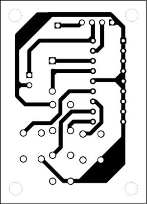 Figure 3: Transmitter unit Solder Side
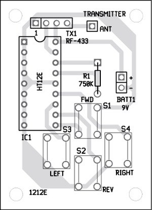 Figure 4: Component Side Transmitter Unit PCB
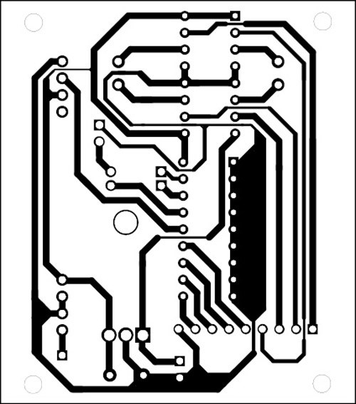
Figure 5: Solder Side Receiver Unit PCB
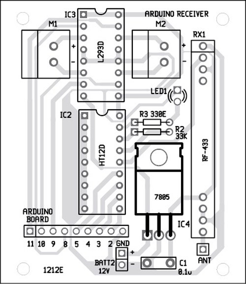
Figure 6: Component Side Receiver Unit PCB
CLICK HERE TO DOWNLOAD PCB DIAGRAM
Software
At the end of this project, you can see the link to get the source code file of the project (RFROBOT.INO). It is well known that the Arduino Uno device is programmed with Arduino IDE software. IT is much easy to upload new code to the Arduino without the help of an external hardware programmer since the microcontroller ATmega328 on the Arduino Uno is pre-burned with a bootloader initially. For communication, it employs STK500 protocol. However, one can ignore the bootloader and feed the program into the microcontroller through the ICSP (in-circuit serial programming) header. To complete the project in time and make it easy, it is considered wise to use a bootloader.
CLICK HERE TO DOWNLOAD SOFTWARE CODE
PARTS LIST OF ARDUINO AND RF CONTROLLED ROBOT
| Resistors (all ¼-watt, ± 5% Carbon) |
| R1 = 750 KΩ
R2 = 33 KΩ R3 = 330 Ω |
| Capacitors |
| C1 = 0.1 µF (Ceramic Disc) |
| Semiconductors |
| IC1 = HT12E (Encoder IC)
IC2 = HT12D (Decoder IC) IC3 = L293D (Motor Driver IC) IC4 = LM7805 (5V Regulator IC) LED1 = 5mm Any Color LED TX1 = 433MHz RF ASK Transmitter RX1 = 433MHz RF ASK Receiver ARD1 = Arduino Uno Board |
| Miscellaneous |
| SW1 – SW4 = Push—to-on tactile Switch
M1, M2 = 12V, 100-RPM Geared Motor BATT1 = 9V Battery BATT2 = 12V Battery |