Recently we have been posting Robot projects. And, here comes another one; Robocar with gesture-controlled or you can say Arduino Gesture Controlled Robot. Like other projects, it also employs remote control.
The project Arduino Gesture Controlled Robot is concerned with the design of a robotic car that can be moved in any direction just like a car does. Motion is recognized by the accelerometer and then it generates command signals to operate the robot as required using RF as a mediator. Likewise, the Robocar has inbuilt obstacle detectors and avoids features that provide a more realistic approach to the concept.
Other Robotic projects posted in bestengineeringprojects.com
- Arduino based Bluetooth Controlled Car
- PIC16F877A Based Dual-Mode Robot
- Arduino and RF Controlled Robot
Circuit Description of Arduino Gesture Controlled Robot
An accelerometer is used as a motion sensor for steering. Its output is fed to the Arduino Uno Board and after processing the data, the corresponding command is passed to the robot control through the RF transmitter. The MCU unit of the robot acts accordingly and drives the motor. When any obstacles are detected on the way, the microcontroller stops the forward motion.
The respective figure of the Arduino Gesture Controlled Robot is shown in Fig. 1 and 2.
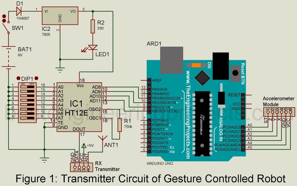
Gesture Controlled Circuit
This portion is centered around Arduino Uno Board(Board1). Encoder HT12E (IC1), regulator 7805 (IC2), 433MHz RF transmitter module, accelerometer module, and a few discrete components build up the gesture-controlled section. The connection between the Uno board and accelerometer is done in the following ways:
| Arduino Uno Board | Accelerometer module |
| A0 | ST |
| A1 | Z-axis |
| A2 | Y-axis |
| A3 | X-axis |
| A4 | GND |
| A5 | VCC |
The microcontroller in the Uno board receives data from the accelerometer and the data on the axes of the accelerometer are compared with the default values of each axis. In case, when the values don’t match up, a 4-bit code is produced at pins 8-11. IC1 encodes the code and then transmits the data through the RF transmitter module.
Accelerometer module.
This module is responsible to measure acceleration. For this project, an ADXL335 triple-axis accelerometer is included with a sensing range of ±3g.
Robot Section of Arduino Gesture Controlled Robot
RF receiver module, decoder HT12D (IC3), microcontroller PIC16F877A (IC4), operational amplifier LM324 (IC5), motor driver L293D (IC6), regulator 7805 (IC7) and a few discrete components shape up the Arduino Gesture Controlled Robot.
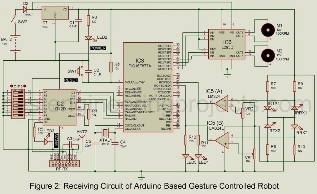
Once the data transmitted by the remote is detected, the RF receiver module fetches the signal and IC3 is responsible for decoding the signal. The data is then passed onto microcontroller IC4 through pins RC0 to RC3. The encoder and decoder are shorted to ground and identical addresses are selected through switches DIP1 and DIP2. Pins RD0-RD3 of IC3 are connected to pins IN1-IN4 of IC6 so as to supply output from IC3 to drive motors M1 and M2 through IC6. To ensure output, enable pins EN1; pin 1, and EN2; pin 9 are maintained at high levels throughout the project.
For power supply, a 12V battery is attached to motor driver IC6 through pin 8. Another IC; IC7 provides regulated 5 supplies for the circuit. As obstacle detectors, two IR transmitter-receiver pairs are included in the circuit. The reference voltage of two operational amplifiers in IC5 is fixed by Presets VR1 and VR2.
As the device approaches any obstacle on its way, the IR beam is reflected back from the obstacle. The outputs of operational amplifiers go high as the reference voltage exceeds the input voltage at the inverting pins 2 and 6 of IC5. This situation is depicted by the glowing LED4 and LED5.
Pins RC5 and RC4 of IC3 are connected to output pins 1 and 7 of IC4. Then the microcontroller operates according to the data received from the transmitter section and obstacle detectors. The encounter of obstacles in one direction will prevent the robot from marching in that direction but it is free to move in other directions.
The working of this Arduino Gesture Controlled Robot circuit is much simple. Take control of Gesture Controlled Remote by placing hands over it and start driving the Robocar like a normal car. Initially, set to the no-movement position by adjusting the tilt. After doing so, moving the steering towards the left alters and exceeds the predefined values of the corresponding axis of the accelerometer, code is generated and is transmitted to the robot control. Then, the receiver circuit commands the microcontroller to drive the motor, and the robocar moves towards the left direction. In the same way, tilt the steering in another direction to move robocar in another direction.
Software of Arduino Gesture Controlled Robot
Arduino Uno is the heart of the circuit. And, thus Arduino IDE software is used as the programming platform. It’s easy to program the ATmega328 microcontroller on Arduino Uno as it has a pre-burnt boot loader. Original STK500 protocol is used for communication. If required, you can upload the program to the microcontroller using ICSP (in-circuit serial programming) header. However, using a boot loader is more convenient. You can directly download the software code from the link below. The Software code folder contains software code for Arduino as well as software code for the PIC microcontroller.
In Arduino IDE, go to ‘Tools → Board’ and pick Arduino Uno (according to the microcontroller on your board) and using the standard USB port in the computer, the program is loaded onto the Uno. For the robot (PIC Microcontroller), the source code is written in the ‘C’ language. It is then compiled using MPLAB IDE. The hex code is generated and is fed to the microcontroller with the help of a suitable programmer. The input and output ports are initialized and then the program is executed. This program monitors the received inputs and instructs the motor driver to move accordingly in forwarding, backward, left, and right directions.
CLICK HERE TO DOWNLOAD SOFTWARE CODE
PARTS LIST OF ARDUINO GESTURE CONTROLLED ROBOT
| Resistors (all ¼-watt, ± 5% Carbon) |
| R1 = 750 KΩ
R2, R5, R6, R11, R12 = 330 Ω R3 = 33 KΩ R4, R9, R10 = 10 KΩ R7, R8 = 100 Ω VR1, VR2 = 10 KΩ Preset. |
| Capacitors |
| C1 – C3 = 0.1 µF (Ceramic Disc)
C4, C5 = 22 pF (Ceramic Disc) |
| Semiconductors |
| IC1 = HT12E (Encoder IC)
IC2, IC7 = 7805 (5V series voltage Regulator) IC3 = HT12D (Decoder IC) IC5 = LM324 (Operational Amplifier IC) IC6 = L293D (Motor Driver IC) IRTX1, IRX2 = IR Transmitter IRRX1, IRRX2 = IR Receiver D1, D2 = 1N4007 (Rectifier Diode) RF TX = ASK Transmitter Module RF RX = ASK Receiver Module LED1 – LED2 = 5mm Any Color LED ARD1 = Arduino UNO Board Accelerometer Module |
| Miscellaneous |
| DIP1, DIP2 = DIP Switch
SW1, SW2 = Push – to – on Switch M1, M2 = 12V, 100-rpm Geared Motor BATT.1 = 9V Battery (PP3) BATT.2 = 12V, 4.5Ah Battery |