Logarithmic Amplifier using Diode and Transistor
- It produces output that is proportional to the logarithmic input
- It is a non-linear amplifier used for amplification or compression of a wide range of input signals for better resolution.
- It can be used direct DB display on a spectrum analyzer.
You may also like: Antilogarithmic Amplifier
Log Amplifier using a Single Diode and Op-Amp
The circuit arrangement for the logarithmic amplifier/converter is illustrated in figure 1. Here a silicon diode D is connected in the feedback path and the current via the diode is dependent upon the output voltage.
Now from the diagram,

Where Is = Saturation Current
VT = Thermal Voltage
 = material constant
If 
Then, 

Now, from the above condition we can write


Now,

 …..(1)
 …..(2)
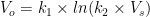
Where,
 and
and 
Hence, V0 is the logarithmic function of input voltage Vin.
It has offset term  and scale factor
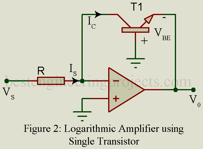
Log Amplifier using a transistor and op-amp
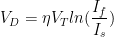
The circuit arrangement for the logarithmic amplifier is illustrated in figure 2. Here the NPN transistor is connected in the feedback path.
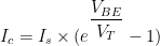
If 
Then, 
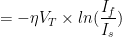
Thus, we can write,

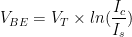


Therefore, 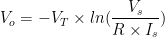 ……(3)
……(3)
Log amplifier using two op-amps and two matched diodes
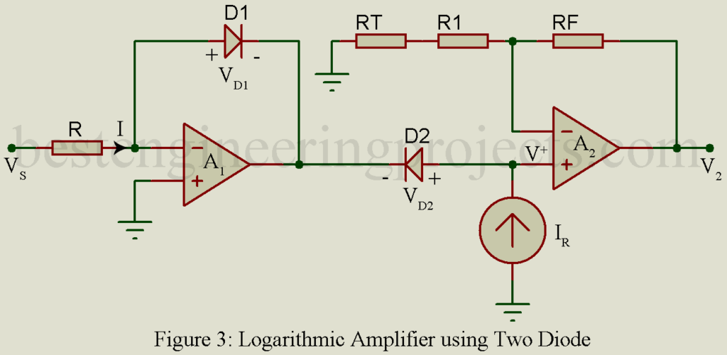
RT = temperature dependent resistor
- This circuit eliminates the saturation term by giving a constant current source.
- Assuming two diodes are matched
For diode

If
Then,
Thus, we can write
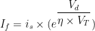
Output diode voltage
 ….(4)
….(4)
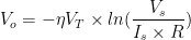
Now, form figure 3


 …..(5)
Similarly,
 ……(6)
……(6)
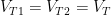
We know that, 
Now, putting the value of IR in the above equation of voltage output of diode.

Assuming both diodes are matched
i.e. 

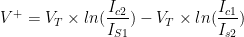
Subtracting equation 5 from equation 6

![= \eta \times V_T [ln(\dfrac{I_R}{I_s})-ln(\dfrac{V_s}{R \times I_s})]](https://s0.wp.com/latex.php?latex=%3D+%5Ceta+%5Ctimes+V_T+%5Bln%28%5Cdfrac%7BI_R%7D%7BI_s%7D%29-ln%28%5Cdfrac%7BV_s%7D%7BR+%5Ctimes+I_s%7D%29%5D&bg=ffffff&fg=000&s=0&c=20201002)
![\eta \times V_T [ln (\dfrac{I_R \times R \times I_s}{I_s \times V_s})]](https://s0.wp.com/latex.php?latex=%5Ceta+%5Ctimes+V_T+%5Bln+%28%5Cdfrac%7BI_R+%5Ctimes+R+%5Ctimes+I_s%7D%7BI_s+%5Ctimes+V_s%7D%29%5D&bg=ffffff&fg=000&s=0&c=20201002)

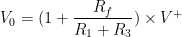
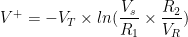
![= [1 + \dfrac{R_f}{R_1 + R_T}] \times [-\eta \times V_T \times ln (\dfrac{V_s}{R \times I_R})]](https://s0.wp.com/latex.php?latex=+%3D+%5B1+%2B+%5Cdfrac%7BR_f%7D%7BR_1+%2B+R_T%7D%5D+%5Ctimes+%5B-%5Ceta+%5Ctimes+V_T+%5Ctimes+ln+%28%5Cdfrac%7BV_s%7D%7BR+%5Ctimes+I_R%7D%29%5D&bg=ffffff&fg=000&s=0&c=20201002)
 …….(7)
- Temperature-sensitive scale factor
 can be compensated by making the gain of Op-Amp (A2) temperature-sensitive.
 - Using temperature-dependent resistor RT in such a way that and RT has an opposite effect and the circuit is independent of temperature.
 can be compensated by making the gain of Op-Amp (A2) temperature-sensitive.
Log amplifier using two matched transistors and two op-amps
- It provides wide dynamic range amplification for input voltage then the diode
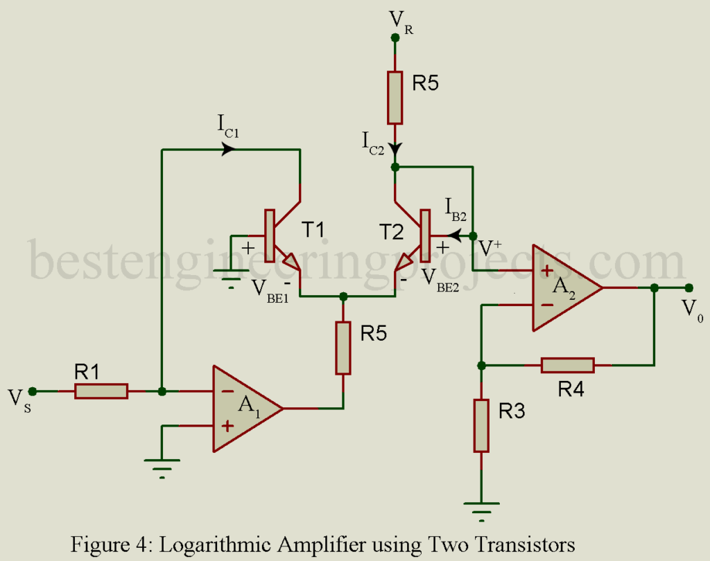
From figure, we can write

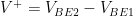 ……(8)
……(8)
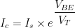
For transistor,
If
Then,
Thus, we can write

Assuming two transistors are matched.


For transistor T1

For transistor T2

From equation 8
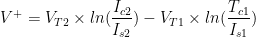


As, is very small and 


- Temperature-sensitive factors can be compensated by making the gain of op-amp A2 also temperature-sensitive by introducing the temperature-dependent resistor so as to make the circuit independent of temperature.