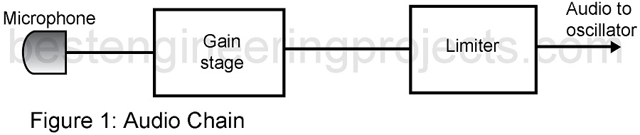
The reactance is efficient and provides a large deviation. It is popular and used often in FM transmitters. Figure 1 illustrates a typical reactance modulator circuit.
Refer to this figure throughout the following discussion. The circuit consist of the reactance circuit and the master oscillator. The reactance circuit operates on the master oscillator to cause its resonance frequency to shift down depending on the modulating signal being applied. The reactance circuit appears capacitive in nature to the master oscillator. In this case, the reactance looks like a variable capacitor in the oscillator’s tank circuit.
Transistor Q1 makes up the reactance modulator circuit. Resistors R2 and R3 establish a voltage divider network that biases Q1. Resistor R4 furnishes emitter feedback emitter feedback to thermally stabilize Q1. Capacitor C3 is a bypass component that prevents ac input signal degeneration. Capacitor C1 interacts with transistor Q1’s inter-electrode capacitance to cause a varying capacitive reactance directly influenced by the input modulating signal.
The master oscillator is a Colpitts oscillator built around transistor Q2. Coil L1, Capacitor C5, and capacitor C6 make up the resonant tank circuit. Capacitor C7 provides the required regenerative feedback to cause to oscillate. Q1 and Q2 are impedance coupled, and capacitor C2 effectively couples the changes at Q1’s collector to the tank circuit of transistor Q2 while blocking dc voltages.
When a modulating signal is applied to the base of transistor Q1 via resistor R1, the reactance of the transistor changes in relation to that signal. If the modulating voltage goes up the capacitance of Q1 goes down, and if the modulating voltage goes down the reactance of Q1 goes up. This change in reactance is felt on Q1’s collector and also at the tank circuit of the Colpitts oscillator transistor Q2. As capacitive reactance at Q1 goes up the resonant frequency of the master oscillator, Q2, decreases. Conversely, if Q1’s capacitive reactance goes down the master oscillator resonant frequency increases.
Troubleshooting the Reactance Modulator
The FM output signal from coil L2 can be lost due to open bias resistors, open RF chokes RFC1 and RFC2, or an open winding at coil L1. In addition, a leaky coupling capacitor C2 may shift the collector voltage of Q2 of the master oscillator, causing a low FM output signal to be present at coil L2. Low collector voltages and weak transistors may produce a low FM signal output condition, as well as changes in bias resistors R2 and R3 in transistor Q1’s circuit and resistors R5 and R6 in Q2’s circuit. Changes in the emitter resistors of both transistor circuit will lessen the FM output and possibly shut the modulator down.
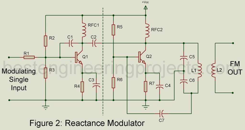
The master oscillator may operate without being influenced by the reactance circuit. The oscillator output signal at L2 would not be FM. This situation could occur if the modulating signal were missing from the base of transistor Q1. An open R1 would block the modulating signal from getting to the base of Q1. Without the modulating signal present. Q1’s reactance would not change. A leaky or shorted C1 could also kill the reactance response of Q1. Transistor Q1 may still be operating perfectly but the reactance changes might not be passed to Q2’s tank circuit due to an open C2.
The following table is a symptom guide to help you troubleshoot the reactance modulating circuit.
|
Table 1 |
|||
|
S.N. |
Symptom |
Problem |
Probable Cause |
| 1. | No signal out from L2 | No FM modulator output | Open bias resistor in Q1 and Q2 circuits; open RFC1 or RFC; C2 open or leaky; feedback capacitor C7 open |
| 2. | No FM output at L2, master oscillator output only | No FM Modulation taking place | Q1 not functioning, check C1, RFC1, and R4; resistor R1 may be open |
| 3. | Amplitude of FM output ow | Low modulator output | Changes in bias resistor values, check R2, R3, R5, and R6; change in emitter resistors, check R4 and R7; Q2’s gain has decreased |
Check the resistors with your DMM for proper value. Resistors in the reactance modulator circuit will be precision types with close tolerance. For low FM signal outputs check capacitors C1, C2, C5, C6 and C7 with a capacitor checker. Any one of these capacitors could cause low output. If any of these capacitors open or become leaky, the FM output may cease altogether. Check coils for open windings using the DMM’s continuity function. Look for cold solder joints by observing a dull appearance of the solder connection. The DMM will give a high resistance indication for cold solder joint.