The most likely types of FM radio a technician will be called to service are an automotive mobile, a fixed base station, or a hand-held portable. Either the mobile or the fixed base station can have power outputs as high as 150 W. Some of these transmitters can be damaged if not operated into the proper load impedance, usually 50-ohm. Some contain automatic circuitry to shut the transmitter off it is not connected to a proper load. Dummy loads are made for this purpose, so make sure you have one rated for sufficient power.
In a FM transmitter, an oscillator is typically controlled so that its frequency changes when an intelligence signal changes. This control is provided by a modulating circuit. in this section we will learn some troubleshooting technique for a reactance modulator circuit.
Frequency-modulated transmitters can be roughly divided into two categories. The first is wideband FM. More popular than AM broadcasting, it is the FM we listen to on our car radios and home stereos (it also produces the audio portion of a TV signal). The second type of FM transmitters is called narrowband FM. It is used in police and file department radio as well as taxicabs and VHF boat radios and the popular hand-held transceivers called handy talkies. We’ll look at testing a wideband FM generator in this section.
After completing this section, you should be able to
- Troubleshoot FM transmitter systems
- Describe the operation of the reactance modulator
- Locate the master oscillator section
- Locate the reactance circuit section
- Recognize the difference between no modulator output, low output, or oscillator output without FM
- Troubleshoot a stereo/SCA FM generator
- Measure and FM transmitter’s carrier frequency and deviation
FM Transmitter Systems
NO RF OUTPUT: In this case, one should first verify that the oscillator is running. Most of these transmitters multiply the oscillator by 12 or 18 to obtain the output frequency. The service manual will tell you what the multiplier is. It is best to have a spectrum analyzer, but a shortwave receiver will do.
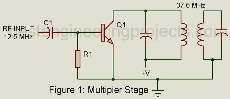
Hints on oscillator problems are already posted previously, so let’s assume that the oscillator is running and move on to the first multiplier stage. Figure 1 shows a simplified schematic of a multiplier stage. If the base-emitter junction is good and there is sufficient input drive, you will find a negative voltage at the base of Q1. This is because the RF input is rectified by the junction and the current flows through R1. When the RF is rectified by the base-emitter junction, current pulses reach in harmonics are amplified and filtered by the tuned circuit in the collector of the transistor.
If the spectrum analyzer is available, the technician can verify that the stage is producing the proper multiple of the input frequency by loosely coupling the analyzer to the output coils. A two or three turn coil ½” in diameter connected to the analyzer will do.
Either the coils or the capacitors will be adjustable. You should be able to peak the output on the proper frequency with these adjustments. If not, check the capacitors and the inductors.
If you do not have a spectrum analyzer, simply measuring the bias voltage on the next stage may be sufficient. You can be reasonably sure that the multiplier is working if you can peak up the drive to the next stage with the adjustments. However, there is some possibility of tuning to the wrong harmonic. If the adjustments are all the way to one end, you may have done this or some component has failed. Another indication of improper tuning is that you will probably not be able to tune the nest stage.
A typical transmitter will have three multiplier stages. At some point in the chain you will be able to find enough signal to run a frequency counter. Be careful, too much input to the counter will damage it. At the output of the transmitter, you can use a high-power attenuator.
INCORRECT FREQUENCY: Most of these transmitters will have trimmer capacitors to adjust the frequency, while-some will have inductors. If the collector is off frequency, check the voltage first, then the capacitors. Intermittent capacitors are the hardest to find. Try cooling the capacitor with an aerosol spray sold for this purpose.
INCORRECT DEVIATION: There are usually two adjustments here, one for microphone gain and one on a limiter. The limiter prevents are user from over-modulating the transmitter. When adjusting deviation, make sure the limiter is adjusted so as not to affect the gain adjustment. Refer to figure 1.
Mobile radios are usually et for a peak deviation of 5 kHz. A good service shop will have a deviation meter. If you don’t have one, a fair job can be done by simply comparing a known good transmitter with the unit under test by listening to both with any receiver.
If a spectrum analyzer is available, recall Carson’s rule and speak into the microphone while adjusting the bandwidth of the transmitter signal to about 16 kHz.
One can also use the zero-carrier amplitude method. While viewing the transmitter output on the spectrum analyzer, apply a 2-kHz tone to the microphone input. Adjust the gain from zero up until the carrier null and you have 5-kHz peak deviation.