Earthquake Detector Circuit using Vibration Sensor
Here, in this article you will find step by step tutorial on earthquake detector and indicator circuit using vibration sensor which detect the seismic vibration of earth and alert by generation beep sound. Previously, we had already posted two different projects on earthquake detection and indication
Earthquake detector using arduino utilize accelerometer in order to detect seismic vibration where earthquake alarm uses geo-mechanical detector. But in the project posted here utilize piezo vibration sensor for MEAS in order to detect seismic vibration.
MEAS (Measurement specialties) vibration sensor can be used for measuring vibration, flexible switch or even frequency response device. Here in this project we had used for vibration measurement of earth and Features of MEAS Vibration sensor
- Can be used as vibration sensor, flexible switch or even frequency response device.
- High operating temperature and voltage
- Withstand high impact
- High sensitive even at low frequency because it is comprising cantilever beam loaded.

Figure 1: MEAS Vibration Sensor
Circuit Description of Earthquake Detector and Indictor
The construction of earthquake detector is very simple and is shown in figure 2. It’s employ few electronic components like arduino uno board, piezo sensor, LCD and buzzer with few passive components like resistors, variable resistors in order to work flawlessly. This project uses arduino uno board which is itself a complete circuit and hence make project easier to implement.
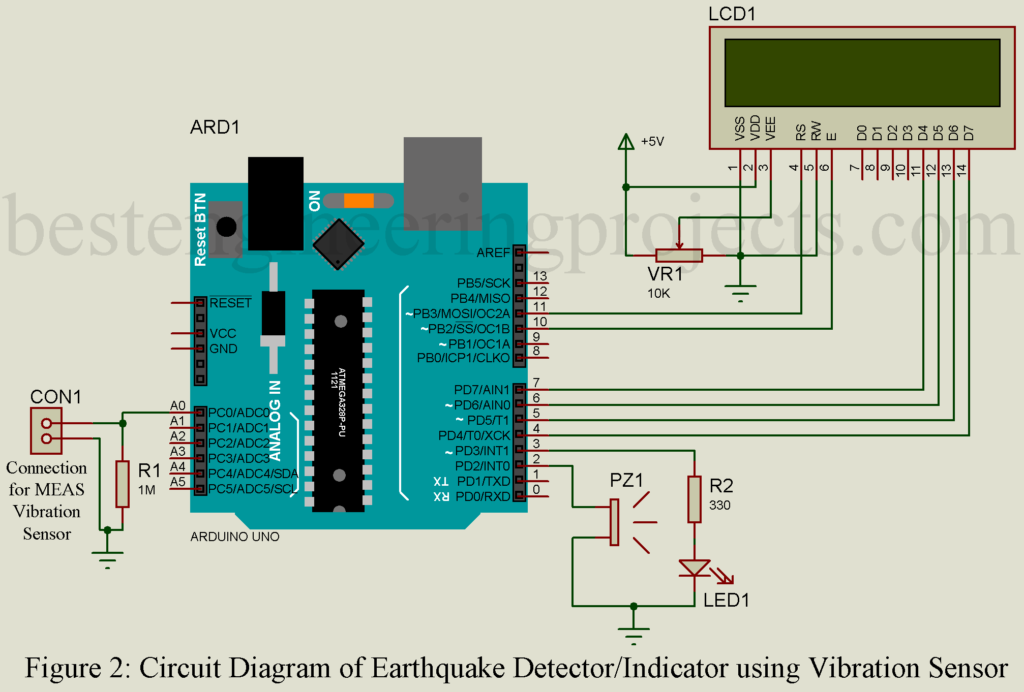
The sensitivity of MEAS vibration is very high thus we can detect seismic vibration of earth easily. When earthquake detector circuit identifies vibration, it is applied with MEAS LDTM-028K sensor produces an analogue voltage equivalent to vibration imposed on it by the seismic vibration. The output pin of vibration sensor is connected to ADC pin of arduino uno board. For any vibration detected, analog output is produced then the inbuilt ADC detects it.
Arduino uno compare the voltage level and display it into LCD. The LCD used here is 16×2 alphanumeric LCD. The LCD is used in 4-bit mode i.e. four higher order bit (D4, D5, D6 and D7) is connected to arduino for data communication. We only perform write operation thus RW (Read/Writ) pin is grounded. Two another pin E (Enable) and RS (Register select) is connector to arduino pin D10 and D11 respectively as shown in circuit diagram. Variable resistor VR1 is used to adjust the contrast of LCD and a current limiting resistor of about 330E must be connected to pin 15 of LCD for backlight (not shown in figure) and pin 16 must be grounded.
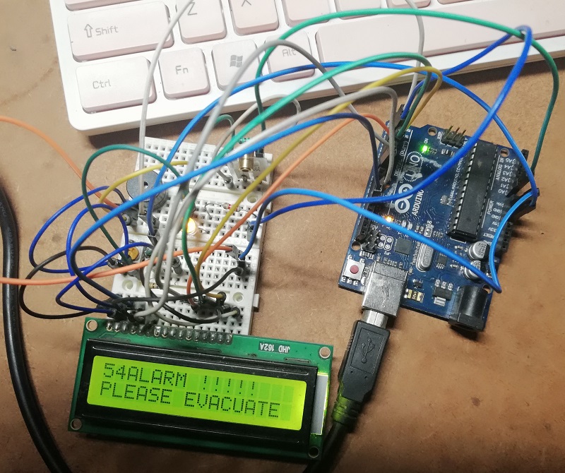
If the vibration is excessive enough to cross a value beyond define threshold value, some preventive action is followed by this circuit.
First, a LED (LED1) glows and a buzzer alarm sound high enough to alert all people around and LCD start to shows warning Message. You can even use a relay in order to switch off any appliance by using relay switching circuit.
NOTE: Fix vibration sensor to wall or Beam of building for best output.
PARTS LIST OF EARTHQUAKE DETECTOR/INDICATOR CIRCUIT
| Resistors (all ¼-watt, ± 5% Carbon) |
| R1 = 1 MΩ
R2 = 330 Ω *R3 = 330 Ω (not shown in circuit diagram, connected to pin 15 of LCD) VR1 = 10 KΩ |
| Semiconductor |
| LED1 = Any color 5mm LED
ARD1 = Arduino UNO Board |
| Miscellaneous |
| PZ1 = Piezo Buzzer
MEAS piezo vibration sensor 16×2 LED |
Software: The software of the project earthquake detector/indicator is very simple to understand. This program is written in arduino programing language and compiled using arduino IDE. The code is shown below:
|
1 2 3 4 5 6 7 8 9 10 11 12 13 14 15 16 17 18 19 20 21 22 23 24 25 26 27 28 29 30 31 32 33 34 35 36 37 38 39 40 41 42 43 44 45 46 47 48 49 |
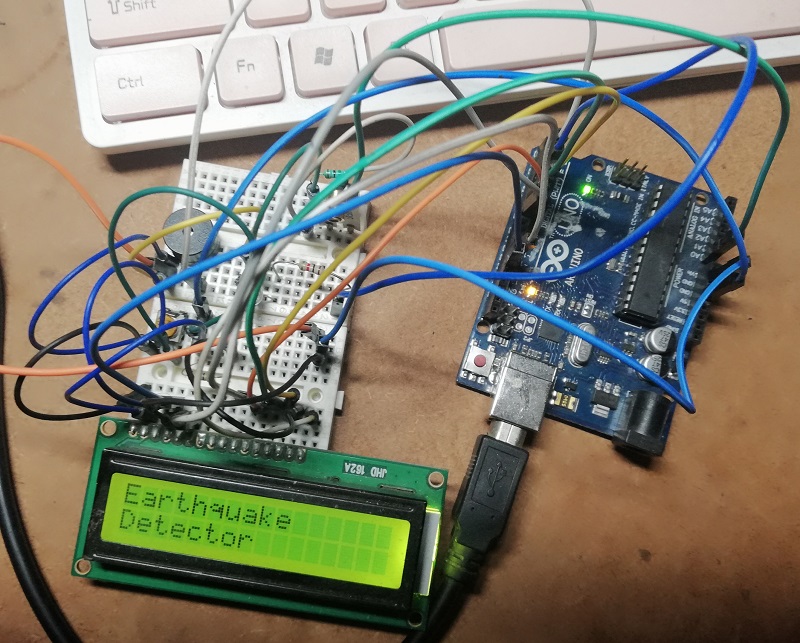
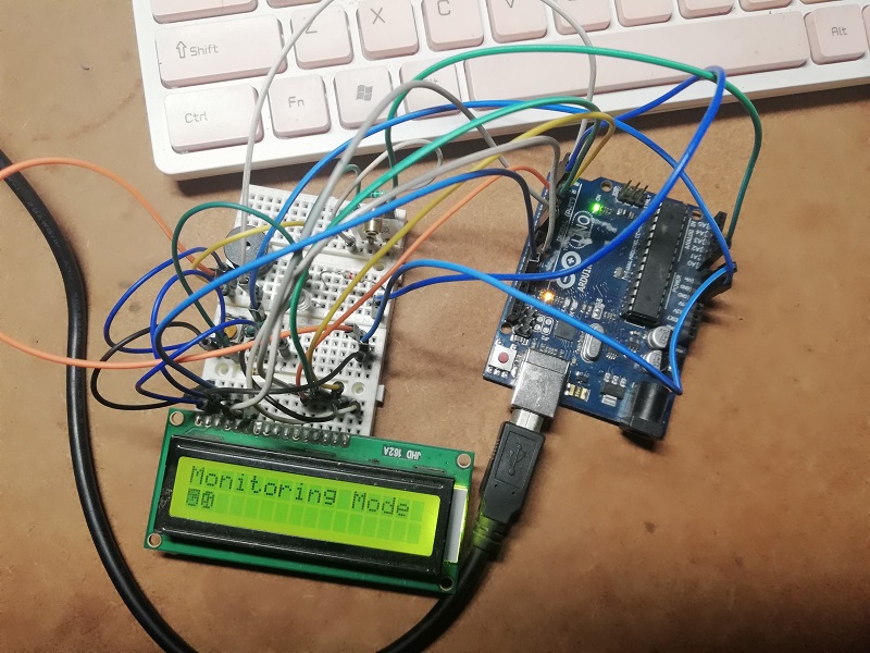
#include <LiquidCrystal.h> const int alarmPin = 2; const int ledPin = 3; const int PIEZO_PIN = A0; int maximum= 50; LiquidCrystal lcd(12, 11, 7, 6, 5, 4); void setup() { // put your setup code here, to run once: Serial.begin(9600); lcd.begin(16,2); pinMode(alarmPin, OUTPUT); pinMode(ledPin, OUTPUT); digitalWrite(alarmPin, LOW); lcd.setCursor(0, 0); lcd.print("Earthquake"); lcd.setCursor(0,1); lcd.print("Detector"); delay(2000); lcd.clear(); lcd.setCursor(0,0); lcd.print("Initializing...."); delay(2000); lcd.clear(); } void loop() { // put your main code here, to run repeatedly: int reading= analogRead(PIEZO_PIN); lcd.setCursor(0, 0); lcd.print("Monitoring Mode"); lcd.setCursor(0,1); lcd.print(reading); if (reading >= maximum) { digitalWrite(ledPin, HIGH); digitalWrite(alarmPin, HIGH); lcd.clear(); lcd.setCursor(0, 0); lcd.print(reading); lcd.print(" ALARM !!!!!"); lcd.setCursor(0,1); lcd.print("PLEASE EVACUATE"); digitalWrite(ledPin, LOW); digitalWrite(alarmPin, LOW); delay(5000); lcd.clear(); } } |