Here is a simple project called earth quake alarm circuit. This circuit is divided into two sections.
- Geo mechanical detector (Earth quake sensor)
- Alarm circuit
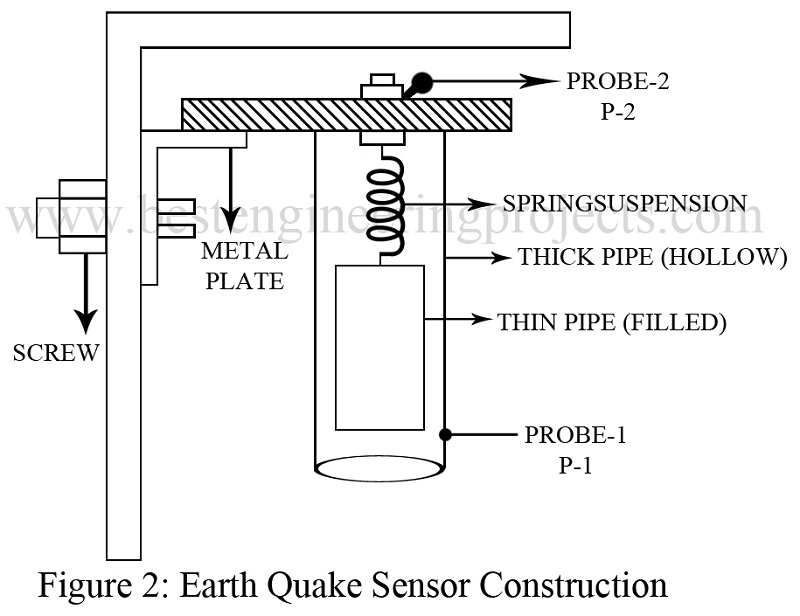
The earth quake alarm circuit is based on the principle that earth quake create slow and suddenly vibration. In order to detect this vibration geo mechanical detector is used. The construction of geo mechanical detector is shown in figure 2.
Alarm Circuit | Earth Quake Alarm Circuit
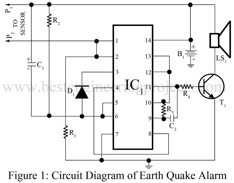
The alarm circuit is built around dual input, 4 NAND IC (CD4011) and a NPN transistor. Input of NAND gate 1 (pin 1) is connected to sensor through probe 1, where NAND gate 2 configured in monostable multivibrator mode. NAND gate 3 and 4 is used as audio oscillator. The output form NAND gate 4 (pin 11) is given to base of speaker driver transistor T1 through coupling resistor R4.
The complete circuit can be kept in cabinet with 9V power supply. The geo mechanical detector where non on can disturb.
Check out other Earthquake Sensor and alarm circuit posted in bestengineeringprojects.com
PARTS LIST OF EARTH QUAKE ALARM CIRCUIT
| Resistor (all ¼-watt, ± 5% Carbon) |
| R1 = 100 KΩ
R2 = 2.2 MΩ R3 = 10 KΩ R4 = 680 Ω |
| Capacitors |
| C1 = 100 µF, 10V (Electrolytic Capacitor)
C2 = 10 KPF (Ceramic Disc) |
| Semiconductors |
| IC1 = CD4011 (Quad 2-Input CMOS NAND Gate IC)
T1 = BC147 (NPN General Purpose Small-signal Driver Transistor) D1 = 1N4148 (Silicon Switching Diode) |
| Miscellaneous |
| LS1 = 8 Ω speaker
B1 = 9V PP3 battery PCB, screw, nuts, metal rod etc. |


Very good circuit’i need photocell using alaram system.
Hey can you please tell me how can the time of this detector be increased from few seconds to a few minutes?