Earthquake Detector using Arduino:- Circuit Diagram, working and circuit description with result and software code including library file of Earth Quake Detector
They say, ‘Prevention is better than cure. This statement goes perfectly with the events whose probability of occurrence is highly possible. Earthquake is one such disaster that comes as an evil fate and sweeps away precious human lives and civilization, it is an unpredictable phenomenon whose occurrence cannot be avoided, but at least we can take measures to minimize the adverse effect of its consequences. In doing so, recent technology plays a vital role. A similar circuit is presented here which acts as an earthquake indicator and prevents further damage. Arduino and a highly-sensitive ADXL335 accelerometer are used to accomplish our goals.
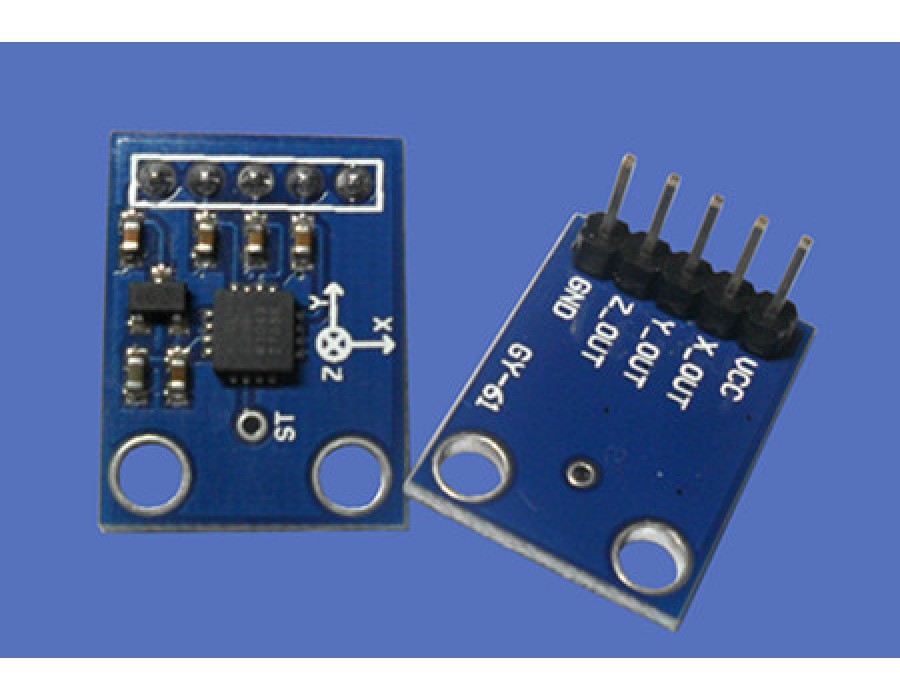
ADXL335 works like a critical sensor in detecting vibrations and predicting earthquakes. The device “Earthquake Detector using Arduino” can sense vibrations and knocks along the three physical dimensions or axes, which makes it more sensitive. Once it identifies vibration, it is applied with acceleration and ADXL335 produces an analog voltage equivalent to acceleration imposed on it by the vibration. The device “Earthquake Detector using Arduino” supplies three outputs along three axes- X-, Y- and Z- axes. These output pins are connected to ADC pins of Arduino Uno. For any acceleration production or vibrations detected, analog outputs are produced by the accelerometer and then the ADC detects it.
You can also check another interesting article on earthquake detector | indicator circuit using MEAS vibration sensor.
In the Arduino uno, voltage levels are compared. In cases of earthquakes, where the movement is excessive enough to cross a value beyond a defined threshold value and create a large impact, some preventive actions are followed. Firstly, a LED glows and a buzzer alarm sounds high enough to alert all the people about the scenario and relay energizes. Out of these three devices, the LED and buzzer fit perfectly for earthquake indication at home whereas the relay is a must for industrial applications.
Relay is wired to a PLC to ensure safe interlocking of any operating machinery part and furnace control to shut them down to avoid accidents due to earthquakes. To implement this concept, threshold adjustment buttons are fitted next to machines to initiate necessary tasks when needed. LCD works as an informer by displaying the threshold adjustments information. It adds the next pile to the flexibility of the project.
Circuit and working of Earthquake Detector Using Arduino
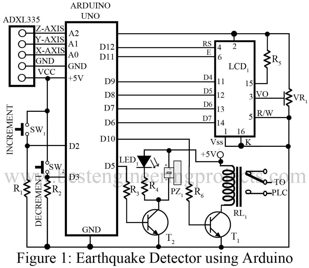
The construction of the project “Earthquake Detector using Arduino” is so simple, that it looks like the assembling of a few common electronics components. The fact that the project “Earthquake Detector using Arduino” uses Arduino Uno, which is itself a complete circuit, makes this project easier to implement. The Arduino board and ADXL335 accelerometer module are interfaced (connected across CON2) properly. The ADC inputs of the accelerometer are connected to Arduino pins in the given pattern: X-axis to A0, Y-axis to A1, and Z-axis to A2.
To externally adjust the threshold value for vibration detection, we have added two extra pushbuttons to the circuit. These buttons are connected across the 5V supply and then connected to the interrupt pins 2 and 3 of Arduino uno, which are further grounded through resistors R2 and R1. For displaying the information, a 16*2 LCD (LCD1) is employed. The LCD is set in 4-wired mode with its default state enabled (i.e. backlight and contrast pin). Both the components; LED and buzzer connected across CON4 need switching and for this transistor T2 (BC548) is connected at the pin 5 terminal of Arduino.
There are cases when we need to de-energize the relay (RL1) when alarms are triggered during industrial PLC interfacing for safety interlocks. And, an extra transistor (BC548) T1 is connected across pin 10. All Arduino pins from 6-9 and 11-12 are configured for LCD control operations and data lines. Under steady conditions, when the supply is continuously fed to the circuit, the status of the accelerometer is monitored at every instant and then each value is stored in Arduino’s internal EEPROM regardless of its orientation.
To use 10-bit ADC, a different header file is tagged along for programming in the code. Since the ADC is 10-bit, a special header file has been provided with the code. Stability is a must in the project “Earthquake Detector using Arduino” to ensure precise reading and therefore the approximately five-second delay is fixed so that all voltage levels and the system could maintain a stable state before initial values are read and collected.
These values are gathered around the three respective axes of the accelerometer, which are then fed to the Arduino. The microcontroller fixed in the Arduino board accepts those readings and then stores them in the EEPROM as stated earlier. The threshold value of reading is also stored in the same location i.e. EEPROM which makes it easy to fetch data for comparison. In this project, the default threshold value is set to 25.
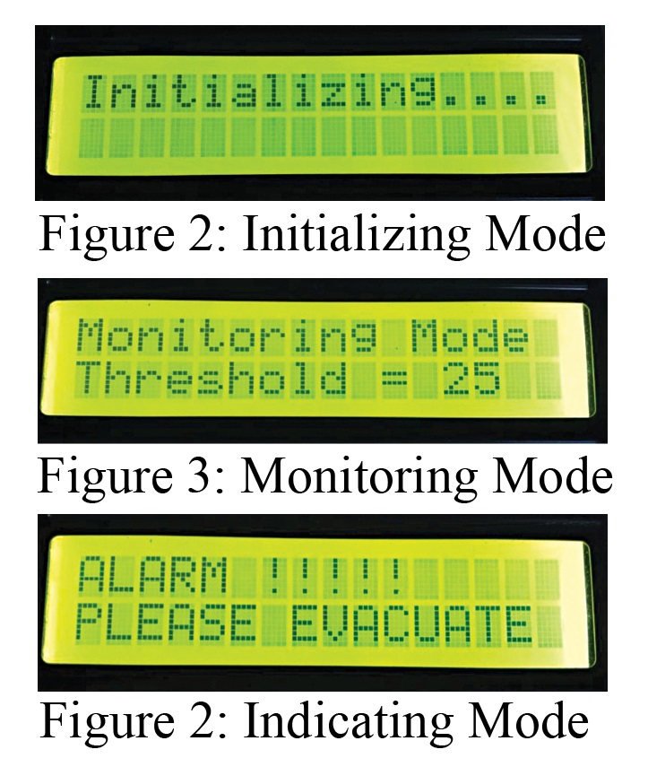
LCD performs an information displaying function. Since it illustrates multiple data, its working can be sectioned into three distinct categories: initializing mode, monitoring mode, and indicating mode which is further discussed in the points below:
- Initializing mode: Multiple parameters are to be considered in this project ie. Temperature, soil moisture, etc. All considered parameters are initialized in this mode. It is shown in fig. 3
- Monitoring mode: In this mode, values of the parameters are continuously monitored at every interval and the fixed threshold value is displayed on the second row of the LCD for comparison.
- Indicating mode: This is the main part where the values are continuously read and then the necessary comparison is done between the standard threshold set in the EEPROM and field values read by the accelerometer. If variations are observed in the values under comparison i.e. stored value by the accelerometer is either greater (along the positive side) or less (along the negative side) than the preset threshold, the alarm is triggered. And, the relay gets de-energized. The program code also supports the negative values in all three axes along with the positive values.
As we can see, push buttons also serve as interrupts being connected to pins 2 and 3 of Arduino so that necessary sensitivity adjustments can be made to increase or decrease threshold values by pressing those buttons. Being an earthquake-based project, a 10-15 value is claimed to be the optimum threshold value here. By setting this value up to 5 to 8, we can modify this project to be used in the detection of knocks and vibrations.
The project “Earthquake Detector using Arduino” is highly sensitive and so it must be carefully fabricated. We can also set this project within a protective hard enclosure and then fix it in any place in the industry or home. Further the project “Earthquake Detector using Arduino” can also be operated in terms of acceleration. Firstly, determine resultant acceleration by using the formula of the square root of X2+Y2+Z2, where X, Y, and Z are corresponding coordinates outputs obtained from ADXL335. Now, compare the result calculated with the preset threshold. And, the same process follows on-wards. If desired, the user can use the same project to perform this change and evaluate the differences in using the two methods.
Software:- Click Here to Download Software
PARTS LIST OF EARTHQUAKE DETECTOR USING ARDUINO
| Resistor (all ¼-watt, ± 5% Carbon) |
| R1, R2 = 10 KΩ
R3, R6 = 1 KΩ R4, R5 = 330 Ω VR1 = 10 KΩ |
| Semiconductors |
| Arduino Uno
T1, T2 = BC548 ADXL335 Accelerometer |
| Miscellaneous |
| SW1, SW2 = Push-to-On Switch
PZ1 = Buzzer LCD1 = 16*2 LCD RL1 = 5V 1C/O Relay LED1 = Any color LED |


