Greenhouse Automation System | Automated Green House: Complete Circuit Diagram using P89V51RD2 microcontroller, Source Code, Working Principle, and Complete Description
Introduction to Greenhouse Automation System | Automated Greenhouse
Technologies have almost reached everywhere, be it in the technical fields or the agricultural fields. One of the specified sectors where this technology has created great impact is Green House, as we call it. Modern technologies are used to monitor certain environmental conditions which is a must to ensure optimum growth of plants in the greenhouse, enhanced crop productivity along proper utilization of water and other resources.
These conditions variables must be well defined and the data regarding soil conditions, and climatic condition parameters that affect the plant development, must be carefully collected through automated processes. Doing so makes it possible to obtain a large number of data at high frequency with less human assistance involved. Though the PC and SMS- based systems are proven suitable to keep the user updated with the greenhouse status, multiple factors make it not worth of investments we make. These factors include expensive prices, bulky size, maintenance issues, and uselessness to unskilled workers.
And, so we decided to try this out “Greenhouse Automation System | Automated Greenhouse” and make things work in a way applicable for us with less amount of physical as well as economical investment. The only focus of this project is to develop such a system/device which is structure-wise much simpler yet easy to install and cheaper. Thus, the project “Greenhouse Automation System | Automated Greenhouse” has employed easily available components like microcontroller as its chief element that is used to monitor and collect the varying greenhouse details such as temperature recordings, a measure of soil moisture and sunlight, at different instants of time. Doing so will assist in maintaining the greenhouse and promote productivity.
The reason why the use of a microcontroller in this project is much appreciated is also because of its low power consumption and reasonable cost besides easy availability. The fact that the microcontroller works through a real-time phenomenon adds an extra pile to its benefit. It interacts with multiple sensors associated with the project “Greenhouse Automation System | Automated Greenhouse” on a real-time basis and keeps control of lighting, aeration, and drainage functions accordingly as per the requirement of the crops by triggering corresponding devices which can be: a cooler, fogger, dripper and lights, etc.
Since this project keeps track of real-time data, the use of an integrated Liquid Crystal Display (LCD) is not an exception. LCDs the collected data and forwards the data to a remote computer through a serial transmission process. There, a complete process of data logging maintenance occurs. The software can be updated a regular time intervals which further extends the flexibility of this project to meet the user requirements.
All these features combined as a whole produce an easy, cost-effective, portable, and easy maintenance alternative for greenhouse applications, beneficial for small-scale agriculture sectors in remote areas.
Working of Greenhouse Automation System | Automated Greenhouse
We are discussing is a basic embedded system that keeps a record of certain parameters of the greenhouse, mostly climatic parameters, and continuously monitors those specifications at regular intervals. The idea not only enhances the greenhouse cultivation process and productivity but also reduces the human effort invested and prevailing issues to a greater extent. In this project, simple components like sensors, microcontrollers, ADC (Analog to Digital Converter), actuators are employed which makes it more cost-effective.
At ordinary conditions, the system “Greenhouse Automation System | Automated Greenhouse” remains active monitoring the climatic condition, as soon as the sensor fitted at several spots start detecting variation in the continuously monitored factors like temperature changes, the project compares it with the threshold value set in the program and takes necessary actions. In technical words, when the sensor detects changes, the microcontroller gets activated and it reads data collected from the sensor at its input terminal. By then, the ADC had already converted the analog data into presentable digital form. As per the requirement, the microcontroller triggers corresponding relays to settle the environmental conditions and those parameters reach the best possible state.
The use of a microcontroller, LCD, and continuous data logging process makes this project more cost-effective and user-friendly at the same time. Hence, this project completely eradicates the necessity of setting up the environmental conditions through effort and offers a flexible system.
Circuit Description of Greenhouse Automation System | Automated Greenhouse:
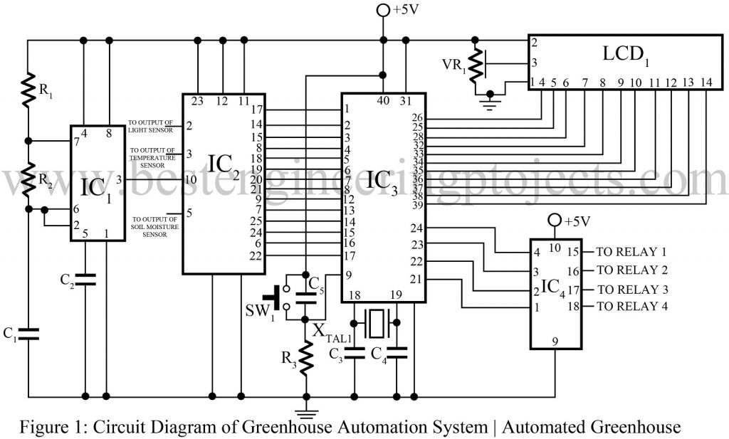
The Circuit diagram of the control unit of the Automated green House is shown in figure 1. Here we described each section separately as given below.
TRANSDUCERS (Data acquisition system) | Greenhouse Automation System | Automated Greenhouse
In this section, different sensors are used to measure the soil moisture, humidity, temperature, and light intensity. And, then the sensed data is transferred to ADC for conversion.
- Functional description of Soil moisture sensor:
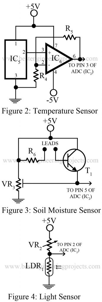
The circuit diagram of soil moisture is shown in figure 4. To sense the soil moisture, we make use of two copper leads immersed into the specimen soil whose moisture content is to be tested. Three conditions are set to examine the state of the soil:
Case 1: Dry condition- In this case, two copper probes are dipped into the dry soil up to a fair depth. In absence of a path for conduction in between the copper leads, the sensor circuit is not complete and hence 0 to 0.5 V is obtained as output.
Case 2: Optimum condition- In this case, the soil is wet to some extent. As the soil absorbs the water, it penetrates the successive layers of the soil, and due to the existing capillary force; it gradually spreads across the soil layer. As a result, the soil moisture increases and increases the conductivity strength of soil that establishes the conductive path between the probes. And, thus current starts flowing in between supply and transistor through the path just constructed. In such a case, the voltage detected at the emitter output of the transistor is found to be in the range of 1.9V to 3.4V nearly.
Case 3: Excess water condition- it is that situation when the water content in the soil exceeds the optimum level. In that case, there is an extreme increment in the conductivity property due to excess water. Because of this, a steady conduction path is formed in between the probes of sensors and after a certain limit, the output voltage is saturated to a constant value. The maximum output is found to be 4.2V.
b. Temperature Functional description:
A large number of components are used in this project, their values must be appropriate to suit our requirements. The circuit diagram of the temperature sensor is shown in figure 2. The sensor used in this project possesses sensitivity of 10mV / 0C. An LM324 single power supply (+5V) op-amp which has a gain of 5 is used to amplify the output of LM35. The resolution for temperature measurement is set up to 0.5 degrees Celsius. A simple conversion factor is used to transform the output voltage to temperature. And, this factor is given by the expression;
Temperature (ËšC) = (Vout * 100 )/ 5 0C
For Vout=5V,
Temperature = 100 ËšC
The voltage and temperature share a linear relationship.
c. Light Sensor: The circuit diagram of the light sensor is shown in figure 2.
ANALOG TO DIGITAL CONVERTER (ADC) | Greenhouse Automation System | Automated Greenhouse
It receives the analog data sent by the sensors and then performs necessary actions to convert it into the presentable digital format for further processing.
ADC, Analog to Digital Converter is an inseparable part of this project. Here we have used a monolithic CMOS device with an 8- bit analog-to-digital converter, 8-channel multiplexer, and microprocessor compatible control logic, ADC0809 component. Successive approximation technique is used for conversion process into digital form. Components like high impedance chopper stabilized comparator; a 256R voltage divider with analog switch tree and a successive approximation register characterize a converter. The 8-channel multiplexer has direct access to any of the 8-single-ended analog signals, which makes the project much easier to follow.
By extracting desired features from multiple A/D conversion techniques, a powerful design of ADC0809 has been done. Hence, it supplies outstanding features; high speed, high accuracy, minimal temperature dependence, excellent long-term accuracy and repeatability, and consumes minimal power. All this jointly makes this project perfect for applications from the process and machine control to consumer and automotive applications.
MICROCONTROLLER | Greenhouse Automation System | Automated Greenhouse
As discussed earlier, this is the base of our project “Greenhouse Automation System | Automated Greenhouse”. The digitized data from the sensor is received through configured input pins. Then, those sensed values are compared with the preset threshold value from the program. The microcontroller initiates actions if required based on the comparison. To do so, it triggers the actuators to carry out necessary operations.
Microcontrollers are the base components in most of the electronics projects around which the entire circuit is fabricated. Especially the 8051 families of microcontrollers which are based on architecture are best fitted for embedded control system projects like ours. These microcontrollers cover a wide range of applications, be it in military equipment, automobiles, or a keyboard. These microcontrollers are available in the market from different companies; Intel, Philips, and Siemens. To meet user requirements, further modifications have been made to the microcontroller which includes I2C interfaces, analog to digital converters, watchdog timers, and pulse width modulated outputs.
In the microcontrollers available in the market, different 8051 microcontrollers with clock speed up to 40MHz and voltage requirements down to 1.5 V are presented.
Hence, we see multiple ranges of parts used to fabricate a single microcontroller make the 8051 families best match for the base architecture of a company’s entire line of products. Also, the microcontroller is a multi-functional device, and developers are only required to learn this platform. In this project, another device; P89V51RD2 which is a low-power, high-performance CMOS 8-bit microcontroller with 8K bytes of in-system programmable Flash memory, is used. The fact that it is manufactured using PHILIPS’s high-density non-volatile memory technology and is compatible with the industry-standard 80C51 instruction set and pinout, makes it more efficient for use.
The use of on-chip Flash in the microcontroller allows the program memory to be reprogrammed in-system or by a conventional non-volatile memory programmer. The PHILIPS P89V51RD2 is a powerful microcontroller built up of a combination of a versatile 8-bit CPU with in-system programmable Flash on a monolithic chip. It offers a highly-flexible and cost-effective solution to many embedded control applications.
Not only this, the P89V51RD2 is designed with static logic for operation down to zero frequency, and therefore, it supports two software selectable power saving modes. Under normal conditions, the Idle Mode stops the CPU. And, it allows the operation of RAM, timer/counters, serial port, and interrupt system to continue functioning.
ACTUATORS | Greenhouse Automation System | Automated Greenhouse
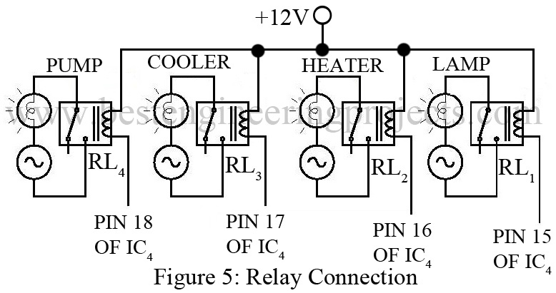
Actuators like relays, contactors, change over switches, etc are employed in the project “Greenhouse Automation System | Automated Greenhouse” (figure 5) which performs triggering operations. Actuators perform the function of triggering AC devices; motors, coolers, pumps, fogging machines, sprayers, etc in the project. We can say actuators work like automatic switches to turn on the devices. The use of relays to drive AC bulbs to simulate actuators and AC devices elaborates the statement. Just by replacing all the simulation devices with actual devices, the working of the entire circuit can be interpreted.
DISPLAY UNIT | Greenhouse Automation System | Automated Greenhouse
The information of “Greenhouse Automation System | Automated Greenhouse” is displayed on two different display platforms:
LCD- Liquid Crystal Display work acts like a mirror that reflects the status of environmental parameters under consideration in a presentable digital form. Since LCD provides real-time information which is continuously monitored and updated corresponding to the changes in the parameters, the reliability of the project is highly reliable.
PC- Besides, LCD that displays information around the vicinity of the greenhouse, information is displayed on another device which is a PC, it allows remote display of data and makes the project more flexible and friendly at the same time. PC receives the data serially from the microcontroller.
DATA LOGGING | Greenhouse Automation System | Automated Greenhouse
To generate data logs for future reference, software like ELTIMA RS232 LOGGER is already installed in the remote pc.
Result of Greenhouse Automation System | Automated Greenhouse
|
Soil Moisture Sensor |
Soil Condition | Optimum Range |
| Dry Soil | 0V – 1.9V | |
| Optimum Level of Soil Moisture | 1.9V – 3.2V | |
| Slurry Soil | >3.2V | |
|
Light Sensor |
Illumination Status | Optimum Range |
| Optimum Illumination | 0V – 0.69V | |
| Dim Light | 0.7V – 2.5V | |
| Dark | 2.5V – 3V | |
| Night | 3V – 3.4V | |
|
Temperature Sensor |
Temperature in 0C | Output in Volt |
| 100C | 0.5V | |
| 150C – 200C | 0.75V – 1V | |
| 200C – 250C | 1V – 1.25V | |
| 250C – 300C | 1.25V – 1.5V | |
| 300C – 350C | 1.5V – 1.75V | |
| 350C – 400C | 1.75V – 2V | |
| 400C – 450C | 2V – 2.25V | |
| 450C – 500C | 2.25V – 2.5V | |
| 500C – 550C | 2.5V – 2.75V | |
| 550C – 600C | 2.75V – 3V | |
| 600C – 650C | 3V – 3.25V | |
| 650C – 700C | 3.25V – 3.5V | |
| 700C – 750C | 3.5V – 3.75V | |
| 750C – 800C | 3.75V – 4V | |
| 800C – 850C | 4V – 4.25V | |
| 850C – 900C | 4.25V – 4.5V | |
| 900C – 950C | 4.5V – 4.75V | |
| 950C – 1000C | 4.75V – 5V |
CLICK HERE TO DOWNLOAD SOURCE CODE
PARTS LIST OF GREENHOUSE AUTOMATION SYSTEM | AUTOMATED GREENHOUSE
| Resistor (all ¼-watt, ± 5% Carbon) |
| R1 = 690Ω
R2, R4 = 1 KΩ R3 = 10 KΩ R5 = 3.9 KΩ R6 = 100Ω VR1 – VR3 = 10 KΩ |
| Capacitors |
| C1 = 2.2 nF (Ceramic Disc)
C2 = 0.01 µF (Ceramic Disc) C3, C4 = 30 pF (Ceramic Disc) C5 = 10 µF (Ceramic Disc) |
| Semiconductors |
| IC1 = NE555 (Timer IC)
IC2 = ADC0809 (Analog to Digital Converter IC) IC3 = P89V51RD2 (Microcontroller) IC4 = ULN2803 (Darlington transistor array) IC5 = LM35 (Temperature Sensor) IC6 = µA741 (Operational Amplifier) T1 = 2N2222 (General Purpose NPN transistor) |
| Miscellaneous |
| XTAL1 = 11.0593MHz
SW1 = Push-to-on Switch RL1 – RL4 = 12V Relay LCD1 = 16*2 LCD LDR |


