Among different types of amplifiers available in today’s technical world, sometimes we get stuck with the audio frequency amplifiers which provide flat frequency low-frequency notes should be amplified more than the high-frequency note stable). The provision of bass treble is accordingly made to gratify the users and to compensate for the effect of noise that comes along with the signal. The bass treble combination is given a single name; tone control.
Circuit Description of Bass Treble Circuit
Talking about the bass treble circuit, it is comparatively much simpler and gainful. The whole bass treble circuit is designed such that it is fitted with any stereo system. Using the power supply from the stereo system itself as the total power supply required for this circuit is only 12-volt DC, the bass treble circuit is reduced and made more effective. In the figure below, we have presented the circuit diagram of one channel only for clarity and also because the other channel has an identical circuit arrangement. In the overall bass treble circuit, the output of the pre-amplifier stage is fed as the input for the left as well as a right channel of the stereo system.
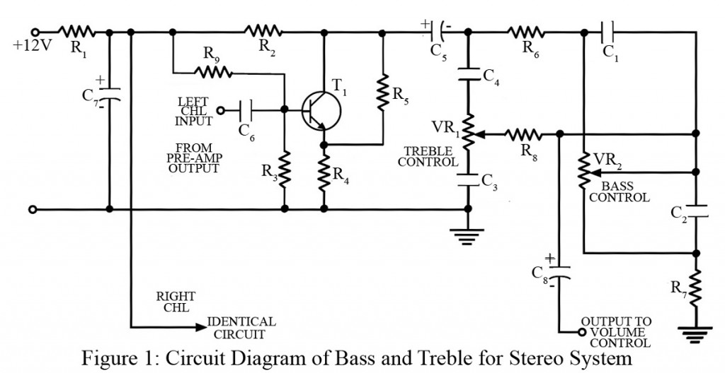
The treble control constitutes the series combination of potentiometer and capacitor named VR1 and C4 in the circuit. To develop a minimum treble signal across the load, the slider of the potentiometer VR1 is pointed at the lower end, The lowest point is referred to as a treble cut. With the proportional increase of slider in an upward direction, the more and more treble signal is picked up. The highest point of increment is referred to as treble boost.
Similar components constitute the bass control. When the slider of potentiometer VR2 is at the upper end, capacitor C1 gets shorted and gets bypassed. Thus, the signal goes directly to the next stage. As a result, the bass has nil attenuation loss) and is called bass boost. But as the slider is lowered and it reaches the lowest end, capacitor C1 is in parallel with the potentiometer VR2. At this stage of the bass treble circuit, the bass will have maximum attenuation, producing the bass cut.
Bass boost and bass cut are effective by it ± 15 dB at 16 Hz, compared to the output at 1 kHz. Treble boost and treble cut are also effective by the same amount at 20 kHz, compared to the value at 10 kHz.
How to monitor the performance of Bass Treble Circuit
Unlike other circuits, the bass treble circuit for the stereo system has an extra advantage with the fact that after assembling the whole circuit, we can monitor the performance of the bass treble system in the following ways:
- Set the slider of potentiometers at their mid-positions.
- Turn on the stereo system.
- Set the volume control of the stereo system at mid-level.
- Set the slider at the position of optimum sound effect.
To add more, the bass treble circuit provides additional help, since it can be easily assembled using a general-purpose PCB.
PARTS LIST OF BASS TREBLE CIRCUIT
| Resistor (all ¼-watt, ± 5% Carbon) |
| R1 = 5.6 KΩ
R2 = 47 KΩ R3 = 270 KΩ R4 = 330 Ω R5 = 1 MΩ R6 = 10 KΩ R7 = 1.2 KΩ R8 = 2.7 KΩ R9 = 68 KΩ VR1, VR2 = 10 KΩ |
| Capacitors |
| C1, C3 = 0.047 µF (Ceramic Disc)
C2 = 0.22 µF (Ceramic Disc) C4 = 3900 pF (Ceramic Disc) C5, C8 = 4.7 µF/16V (Electrolytic capacitor) C6 = 0.1 µF (Ceramic Disc) C7 = 1000 µF/16V (Electrolytic capacitor) |
| Semiconductor |
| T1 = BC147 (NPN Silicon Transistor) |