Power supply has been considered a role in an electronic circuit. Power supply furnishes the voltage and current requirements for electronics circuit operation but the problem is most of the electric power is generated as AC power. But for the operation of most of the electronics circuits, we need a DC power supply. Sometimes the output of the power supply consisting unwanted ripple components i.e. component of supply frequency and its harmonics. We should take care of this unwanted noise or harmonic components because this might cause problems (especially in audio and RF circuit). Sometime this noise may lead to circuit failure. So, to solve this type of issue here, we came up with Noise Free Dual Polarity 12V Power Supply Circuit.
What is the purpose of the dual polarity power supply?
While working with an operating amplifier sometimes we need a negative polarity power supply to generate dual polarity waves (sine wave, square wave, etc.)
Check out other power supply circuits posted on bestengineeringprojects.com
Circuit Description of Noise Free Dual Polarity 12V Power Supply Circuit
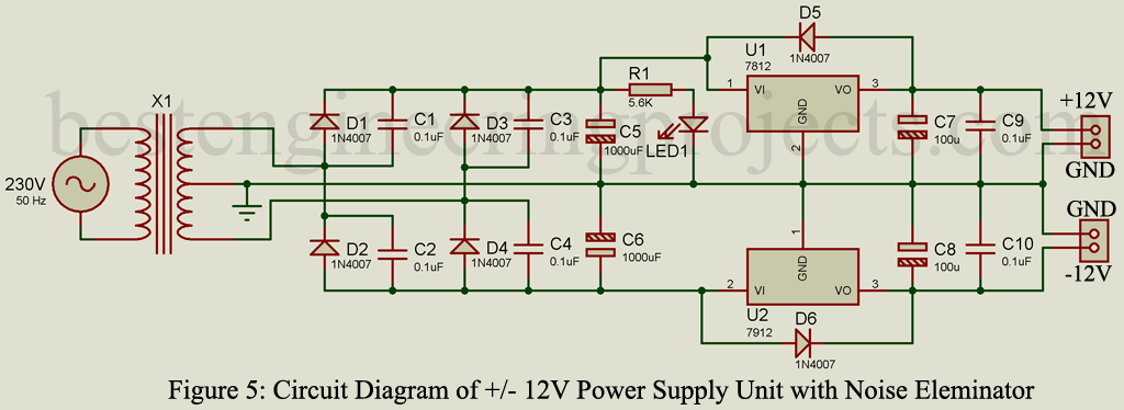
The circuit “Noise Free Dual Polarity 12V Power Supply Circuit” is shown in figure 5, consisting of a center-tap step-down transformer, rectifier diode, linear regulator IC and a few other electronics components.

Figure: Author Prototype
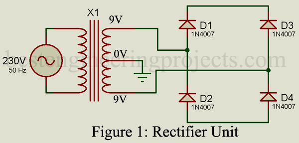
Transformer and Rectifier Unit:
Primary input of transformer is connected to AC mains where secondary output is connected to rectifier input. Two 9V AC mains is connected to the AC input of the rectifier where the 0V terminal is for ground (zero potential). The rectifier circuit is designed using four rectifier diodes. Positive supply is obtained from the cathode junction of diodes D1 and D2 whereas negative supply is obtained from the anode junction of diodes D3 and D4.
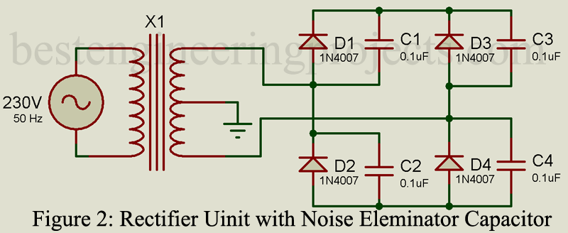
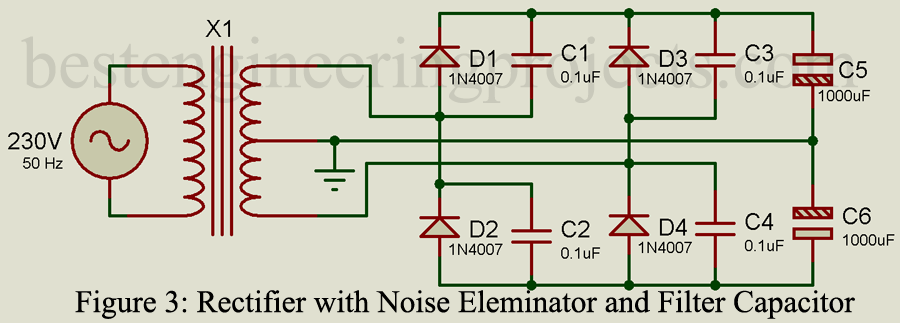
Four ceramic capacitors each of value 0.1uF are connected across each rectifier diode (D1 to D4) to eliminate noise and harmonic available in supply frequency. The output of the rectifier is a D.C. but pulsating in nature. It contains D.C. components and unwanted ripple. This pulsating ripple is removed by the use of a filter capacitor. Two electrolytic capacitors each of 1000uF are connected across the output of the rectifier and ground as shown in the circuit diagram.
Filter Circuit Unit.
Filter Circuit: The filtering power of the circuit is directly proportional to the large value of the capacitor i.e. larger the capacitor better the filtering capacity. But the larger value of the capacitor increases cost and size, thus we have to do a trade-off between these three parameters i.e. filtration power, cost, and size. If you have to design a power supply for an audio circuit then you have to choose better filtering power whereas normal circuit cost and size are preferred. In General, 1000uF is used.
While connecting capacitor C6 we have to consider polarity. Because here we are going to design a negative polarity power supply. Thus, the positive terminal of the capacitor must be connected to ground and the negative polarity to the negative.
Regulator Circuit
After the filtration circuit we need a regulator because of the following reasons:
- When the magnitude of AC mains varies (increases and decreases) output also varies. Let’s consider an example:
Equation of transformer:

Where NP = number of turns on the primary side
NS = number of turns on the secondary side
VP = Voltage at primary side
VS = Voltage at secondary side
If the voltage at the primary side changes (i.e. voltage of mains supply changes) voltage at the secondary side also changes because the turn ratio of winding is constant. Thus, without using a regulator we cannot get constant voltage at the output.
- When the magnitude of load current increases, the output voltage decreases and vice-versa.
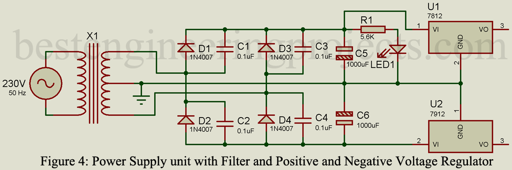
To solve this problem, we are using a linear voltage regulator.
Positive Power Supply: Filtered D.C. positive output is connected to Vin pin (pin 1) of the linear positive voltage regulator (LM7812) where GND pin (pin 2) is connected to Ground. +12V at 1 Amp. Output is obtained from pin 3.
Negative Power Supply: Filtered D.C. negative output is connected to Vin pin (pin 2) of the linear negative voltage regulator (LM7912) where GND pin (pin 1) is connected to Ground. -12V at 1 Amp. Output is obtained from pin 3.
Two electrolytic capacitors each of 100uF and two ceramic capacitor 0.1uF is connected across output to assure stable operation. Diode D5 and D6 are used here as protecting the diode and protect it from reverse voltage.
Parts List of Noise Free Dual Polarity 12V Power Supply Circuit
| Resistor |
| R1 = 5.6k |
| Capacitors |
| C1 – C4, C9, C10 = 0.1uF (Ceramic Disc)
C5, C6 = 1000uF, 35V (Electrolytic Capacitor) C7, C8 = 100uF, 35V (Electrolytic Capacitor) |
| Semiconductor |
| D1 – D6 = 1N4007 (General Purpose Rectifier Diode)
U1 = LM7812 (12V Linear Positive Voltage regulator IC) U2 = LM7912 (12V Linear Negative Voltage regulator IC) |
| Miscellaneous |
| X1 = 230V AC Primary to 9V-0-9V, 2 Amp. Secondary Center-tap Transformer
LED1 = 5mm any color LED Two Heat Sink for Voltage Regulator |