In the project “Arduino Based multiple Device Control using Interrupt” you will learn how to control multiple appliance with two switches by using the concept of interrupt. In this prototype we are going to control four devices using two interrupt pin (switch). You can increase or decrease the number of devices according to your requirement but number of switches is same (two). When button is pressed, interrupt sun-routine is called and control algorithm runs.
Features of Arduino Based multiple Device Control using Interrupt:
- Only two button switches are used to control multiple appliance using the concept of interrupt.
- An I2C LCD is used to show the status of device.
- Simple and interactive design.
Circuit Description Arduino Based multiple Device Control using Interrupt
The circuit of Arduino Based multiple Device Control using Interrupt is build around Seeeduino Nano, I2C LCD, two push button, ULN2003 IC, and few other electronics components like resistor, capacitors and diode. Seeeduino nano board is same as arduino nano but with extra features and comes in less then half price of arduino nano.
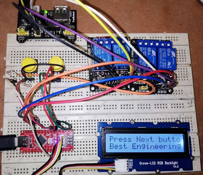 Figure: Author Prototype
Features of Seeeduino Nano
- Size of board is same as arduino nano i.e.43mm x 18mm
- USB type C for programming and power (for symmetrical and reversal).
- On-board Grove I2C connector (you can connect I2C device directly by using grove).
- Cheap in compare to arduino nano.
Check out the link here: Seeeduino Nano
Display Unit:
Here, we are using I2C LCD with grove for easy connection. Two power supply pin VCC and GND of LCD is connected +5V and GND of Seeeduino nano where SDA and SCL pin of LCD is connected to seeeduino nano A4 and A5 (SDA and SCL) of Seeeduino nano. Appliance name and its status is shown over this LCD.
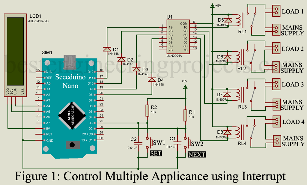
Switching Circuit:
Switching circuit is designed arduino ULN2004 and 5V relay. Digital pin D8 to D11 is used to control the relay through ULN2004 IC. When arduino receive command for appliance ON, arduino pin goes high. Which further make input pin of ULN2004 high through diode and as a result output of ULN2004 become low and relay energized. Similarly, when arduino receive command for appliance OFF, arduino output pin goes low. This low output of arduino pin make ULN2004 pin low and as a result output pin of ULN2004 become high and relay de-energized.
If you wish to design your own Relay switch circuit using transistor then please checkout this article. How to Make Relay Switch Circuit
Two button switches is connected to two interrupt pin of Seeeduino Nano as shown in circuit diagram. RC network (Resistor and Capacitor) is connected across switch in order to compensate Deb-ounce.
Working of the Circuit.
- Assemble all the circuit as shown in circuit. Here, I am using ready made relay module for testing.
- Upload the program to your board.
- A message with “Press Next Button to Procedure” is appeared over LCD. There you have to press Next Button (Switch connect to D2).
- And then Press “Set Switch” (Switch connected to D3) to switch ON the corresponding LOAD. And then again press Next Switch.
Software:
Software is written in arduino programming language and compiled using arduino IDE.
|
1 2 3 4 5 6 7 8 9 10 11 12 13 14 15 16 17 18 19 20 21 22 23 24 25 26 27 28 29 30 31 32 33 34 35 36 37 38 39 40 41 42 43 44 45 46 47 48 49 50 51 52 53 54 55 56 57 58 59 60 61 62 63 64 65 66 67 68 69 70 71 72 73 74 75 76 77 78 79 80 81 82 83 84 85 86 87 88 89 90 91 92 93 94 95 96 97 98 99 100 101 102 103 104 105 106 107 108 109 110 111 112 113 114 115 116 117 118 119 120 121 122 123 124 125 126 127 128 129 130 131 132 133 134 135 136 137 138 139 140 141 142 143 144 145 146 147 148 149 150 151 152 153 154 155 156 157 158 159 160 161 162 163 164 165 166 167 168 169 170 171 172 173 174 175 176 177 178 179 180 181 182 183 184 185 186 187 188 189 190 191 192 193 194 195 196 |
// include the library code: #include <Wire.h> #include "rgb_lcd.h" rgb_lcd lcd; int n = 0; int k = 0; boolean n1 = 0; boolean n2 = 0; boolean n3 = 0; boolean n4 = 0; void setup() { lcd.begin(16, 2); pinMode(2, INPUT_PULLUP); pinMode(3, INPUT_PULLUP); pinMode(8, OUTPUT); pinMode(9, OUTPUT); pinMode(10, OUTPUT); pinMode(11, OUTPUT); digitalWrite(8, LOW); digitalWrite(9, LOW); digitalWrite(10, LOW); digitalWrite(11, LOW); attachInterrupt(0, nbpress, RISING); attachInterrupt(1, sbpress, RISING); lcd.print("Press Next button to start."); lcd.setCursor(0, 1); lcd.print("Best Engineering Projects"); } void loop() { while(n == 0) { lcd.scrollDisplayLeft(); delay(500); } delay(500); } void nbpress() { n = n + 1; if (n > 4) { n = 1; } switchn(); } void switchn() { switch (n) { case 1: lcd.clear(); lcd.print("Load: L1"); lcd.setCursor(0, 1); if (n1 == 0) { lcd.print("Stat: OFF"); } else if (n1 == 1) { lcd.print("Stat: ON "); } break; case 2: lcd.clear(); lcd.print("Load: L2"); lcd.setCursor(0, 1); if (n2 == 0) { lcd.print("Stat: OFF"); } else if (n2 == 1) { lcd.print("Stat: ON "); } break; case 3: lcd.clear(); lcd.print("Load: L3"); lcd.setCursor(0, 1); if (n3 == 0) { lcd.print("Stat: OFF"); } else if (n3 == 1) { lcd.print("Stat: ON "); } break; case 4: lcd.clear(); lcd.print("Load: L4"); lcd.setCursor(0, 1); if (n4 == 0) { lcd.print("Stat: OFF"); } else if (n4 == 1) { lcd.print("Stat: ON "); } break; } } void sbpress() { k++; if(k>1) { k=0; } if (n==1) { if (k == 1) { n1 = 1; digitalWrite(1,1); lcd.setCursor(0,1); lcd.print("Stat: ON "); } if (k==0) { n1 = 0; digitalWrite(1,0); lcd.setCursor(0,1); lcd.print("Stat: OFF"); } } if (n==2) { if (k == 1) { n2 = 1; digitalWrite(8,1); lcd.setCursor(0,1); lcd.print("Stat: ON "); } if (k==0) { n2 = 0; digitalWrite(8,0); lcd.setCursor(0,1); lcd.print("Stat: OFF"); } } if (n==3) { if (k == 1) { n3 = 1; digitalWrite(9,1); lcd.setCursor(0,1); lcd.print("Stat: ON "); } if (k==0) { n3 = 0; digitalWrite(9,0); lcd.setCursor(0,1); lcd.print("Stat: OFF"); } } if (n==4) { if (k == 1) { n4 = 1; digitalWrite(10,1); lcd.setCursor(0,1); lcd.print("Stat: ON "); } if (k==0) { n4 = 0; digitalWrite(10,0); lcd.setCursor(0,1); lcd.print("Stat: OFF"); } } } |