In this article, we will discuss BCD to the decimal decoder and BCD to 7 segment decoder its key parameters, application, and comments.
BCD to Decimal Description:
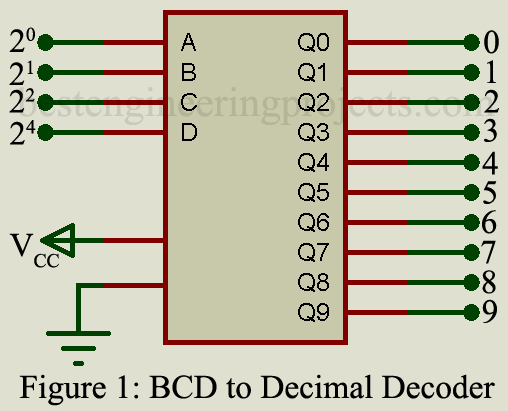
This type of decoder is probably the most widely used in all digital systems because it changes the inherent binary codes used within the system to the decimal code used by the human operators. Figure 1 illustrates the function block of a basic BCD-to-decimal decoder. Four input lines represent the decimal numbers 0 through 9. This type of decoder is often used in combination with decade counters and with decimal displays. By using only, the three least significant inputs, a 3-bit binary-to-octal decoder is obtained, with outputs only on terminals 0 through 7.
Key Parameters
The electrical characteristics are essentially the same as those of the particular digital IC family.
- Quiescent Current: The total current flowing in the IC when no operations are performed. 5.0 nA at a 5V power supply is typically for low-power CMOS.
- Noise immunity: The relation of noise amplitude to VCC. 45% of the power-supply voltage is typically for low-power CMOS.
- Propagation delay time: The time required from the input to the output of the IC. Typically, values are 300 ns at a 5V power supply for low-power CMOS devices.
Applications
BCD-to-decimal decoders are used for code conversion, address decoding, memory selection control, read-out decoding, and de-multiplexing in digital systems such as mini-and microcomputers, digital voltmeters, etc.
Representative Part Number: Fairchild F4028
BCD-to-7 Segment Display Decoder
This type of decoder accepts the BCD information and converts it into seven outputs for connection to a 7-segment display. These numerical displays can be implemented by light-emitting diodes (LED), liquid crystal displays (LCD), gas discharge displays, fluorescent displays, or incandescent displays. The 7-segment outputs may be connected directly only to a low brightness fluorescent display. In all other instances, some kind of driving circuit is required.
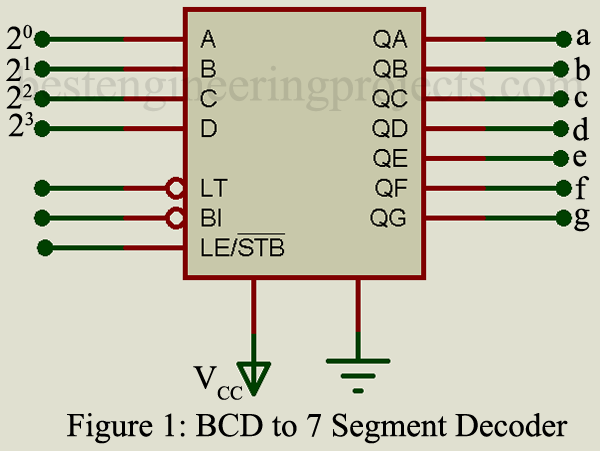
As illustrated in figure 2, there are three additional inputs, not part of the code conversion circuit. When the lamp test input terminal is connected to the ground, all seven segments will be illuminated. The purpose of the blanking in-and-output terminals is to provide a so-called “ripple-blanking” operation. In this mode, a series of 7-segment numerical indicators are illuminated in sequence to reduce the total power requirements. This means that a blanking signal is applied to the “blank” terminal and, after the BCD-to-7-segment decoder has been disabled for a brief period, the output “blank-out” is connected to the next decoder “blank-in.”
Key Parameters
The electrical characteristics are essentially the same as those of a particular digital IC family
- Maximum power dissipation: The maximum power dissipation by the entire IC. 500 mW is a typical value for CMOS.
- Noise immunity: The relation between noise and VCC. 45% of the power-supply voltage is typically for CMOS.
- Propagation delay time: The time from input to output. 450 ns is a typical value at a 5V power supply for CMOS.
Applications
These ICs are used to display BCD information on 7-segment numerical displays. They are found in multimeters, counters, other test equipment, commercial electronic scales, and wherever a numerical read-out is required.
Representative Part Number: Sprague UCN-4102
Comments:
The BCD-to-7-segment decoder described here is often found in a single IC, combined with a counter, latching circuit, and output drivers suitable for the particular type of display.
Check out Encoder and Decoder IC