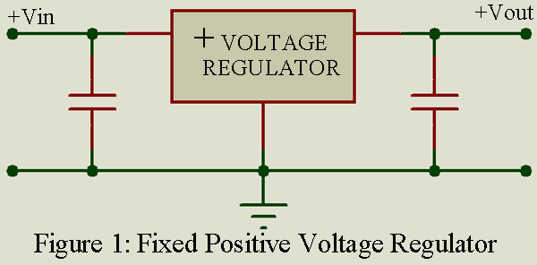
This basic three-terminal device Fixed Output Voltage Regulator is available as either a positive or negative voltage regulator for a large range of fixed output voltages. In figure 1 small capacitor are shown at the input and output of the voltage regulator, because in many applications such capacitors are required to assure stable operation.
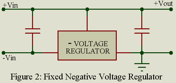
Ordinarily we can obtain voltage regulators of the required polarity but it is also possible, as illustrated in figure 2, to use a negative voltage regulator to provide a regulated positive output voltage.Similar connection can be used for positive voltage regulators to provide negative output voltages. Optimum regulation performance is obtained when the correct polarity voltage regulates are used. Fixed output regulators are frequently used with external transistors to handle larger regulated output currents.
Key Parameters Fixed Output Voltage Regulator
Output Voltage: The regulated output voltage maintained over the specified operating range. Popular values are 5, 12, 15, 18 and 24 volts.
Input voltage: Range of input voltages for which the regulated output voltage is maintained. Depending on output voltage, 7 to 30 volts are typical values.
Line regulating: The change of output voltage for a corresponding change in input voltage. Often stated in millivolts for 1-volt changes, a typical line regulation is 0.1% per volt.
Load Regulation: The change in output voltage for a corresponding change in output current. A typical value is 0.1% over the specified range of load current.
Output Voltage Temperature Coefficient: The change in output voltage per degree change in junction temperature. Sometimes stated as millivolts per degree C change. Typical values are of output voltage per degree C.
Output current range: The minimum output current to maintain regulation and maximum output current. Actual values depend on the specific IC, but a range of 100:1 is typical.
Maximum operating junction temperature: The maximum temperature at which the IC voltage regulator can operate safely. Most commercial ICs are rated for 1500C.
Maximum power dissipation: Maximum power the IC can dissipate at 250C (room temperature) without a heat sink of forced air cooling. Commercial ICs can handle from 100 milliwatts to 50 watts. More than 2 watts usually requires an external heat sink.
Safe operation area (SOA): The area under a curve that describes the maximum safe operating characteristics. For fixed output voltage regulators, the SOA is usually not as important as for variable output devices.
Applications of Fixed Output Voltage Regulator
As voltage regulators where the output voltage is fixed and usually required in standard values. Digital systems using standard logic families often require sample, fixed output voltage regulators at various points in the system.
Representative Part Number: National Semiconductor LM7812, LM7912.
Comments
It is possible to get some adjustment of the regulated output voltage even with a fixed output voltage regulator. Some external circuitry, including an op-amp and some resistors, can be connected to provide some adjustment, but it is generally more cost effective to use an adjustable type voltage regulator.
Positive and Negative 12V Power Supply
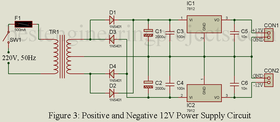
The circuit of 12V positive and negative power supply is shown in figure 3. This circuit is designed around two fixed voltage regulator IC i.e. LM7812 and LM7912 for positive and negative 12V respectively. 220V AC mains supply is given to primary input of center tap step down transformer. 12V-0-12V AC is obtained form the secondary winding which is converted into DC using bridge rectifier. Bridge rectifier is designed using four rectifier diode (D1 to D4). The DC output from bridge rectifier contains ripple, which is filtered using two capacitors C1 and C2. These capacitors filter the ripple contains in DC. Thus the output voltage of capacitor is pure DC but not regulated.
Here, we are using two regulator one for positive power supply and another for negative power supply. Positive pure DC from positive terminal of capacitor C1 is connected to Vin pin (pin 1) of positive voltage regulator IC (IC1) where negative DC volt form negative terminal of capacitor C2 is given to Vin pin (pin 2) of IC2. Ceramic capacitors C5 and C6 is connected to output pin of both voltage regulator IC. Positive 12V is obtained from CON1 where negative 12V is obtained for CON2
Components required
IC1 = LM7812
IC2 = LM7912
D1 – D4 = 1N5401
C1, C2 = 2000 uF/35V
C3, C4 = 100 nF
C5, C6 = 10 nF
TR1 = 220V to 12V-0-12V center tap transformer
SW1 = ON OFF Swith
F1 = 500mA Fuse
CON1, CON2 = Two pin connector
Check out other top popular Articles :
Clock Signal Generator Circuit


