In the post-Arduino alarm clock with time setting you will learn to make a digital clock using the RTC DS3231 module with alarm and temperature indication facility. Previously, we had already posted various types of clock circuits using Arduino and RTC DS3231 like “Arduino NTP Clock using NodeMCU and DS3231”, “Arduino Digital Clock using DS3231 Pi Module“. Before starting to circuit part and software code part let’s see its features:
Features of Arduino alarm clock with time setting
- Display date and time (day and second indication).
- Alarm time setting
- Display temperature without using a dedicated temperature sensor.
- Can adjust time according to your requirement
- Dedicated four pushbuttons for time and alarm time setting.
Component required for Arduino alarm clock with time setting
- Arduino UNO Board x 1
- RTC Module DS3231 x 1
- 16×2 LCD x 1
- Push-to-on Switch x 4
- Buzzer x 1
- 470-ohm resistor x 1
- 10k-ohm Variable resistor x 1
Circuit Description of Arduino alarm clock with time setting
The circuit is shown in figure 1, built around the Arduino Uno board, etc module, 16×2 LCD, and a few other electronic components. LCD is connected in higher-order mode i.e. higher-order digital pin of LCD (D4 – D7) is used to receiver the data to display. LCD Pin D4, D5, D6, and D7 are connected to Arduino digital pin D7, D8, D9, and D10 respectively as shown in the circuit diagram. Reset/Set (RS) pin of LCD is connected to Arduino digital pin D12 where enable pin (E) of LCD is connected to D11 of Arduino. Vss, RW, and LED- pin (i.e. LCD pin 1, 5, and 16) is connected to the ground potential where VDD pin (Pin 2) of LCD is connected to +5V supply from Arduino.
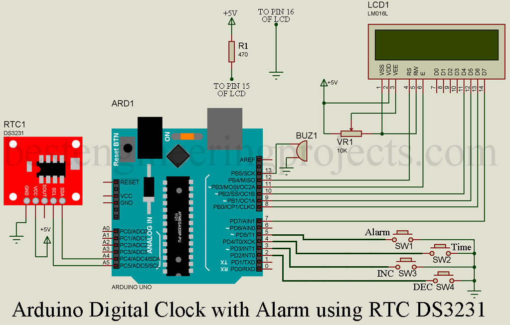
VEE pin (pin 3) of LCD must be connected to lower potential than VDD and higher potential than the ground. Thus, we are using a variable resistor VR1 of 10K, on the fixed terminal of the variable resistor VR1 is connected to +5V where another fixed terminal is connected to the ground. The wiper or variable pin of the variable resistor is connected to pin 3 of the LCD. The voltage at this pin (pin 3) is responsible for LCD contrast. If the LCD does not show any characteristic adjust the variable resistor. LED+ pin (pin 15) of LCD is also connected to +5V through a current limiting resistor R1 (470-ohm). LED+ and LED- pin is for the backlight of LCD.
If you have any difficulties on interfacing LCD with Arduino then please do watch the making video of “Tutorial on Interfacing of 16×2 LCD to Arduino”.
RTC module DS3231 uses the I2C protocol for communication, thus we are using the SDA and SCL pin (A4 and A5) of Arduino. There are various regions of using DSD3231 over DS, a few of these reasons are listed below.
1. No external crystal thus higher accuracy.
2. Inbuilt temperature sensor
3. External temperature does not affect much.
For this prototype, we are using the DS3231 Pi model. + pin and – pin of DS3231 is connected to +5 volt and ground respectively. Where D and C pin is connected to SDA and SCL pin (Pin A4 and A5) respectively as shown in the circuit diagram.
Four Push-to-on switches are used to adjust the time and alarm connected to Arduino digital pin D2 to D5 as shown in the circuit diagram. Instead of using an external pull-up or pulldown resistor, we are using an internal pull-up resistor as defined in software code.
| S.N. | Switch | Remarks |
| 1.
2. 3. 4. |
SW1
SW2 SW3 SW4 |
Set Alarm Time
Set Date and Time Increase Value Decrease value |
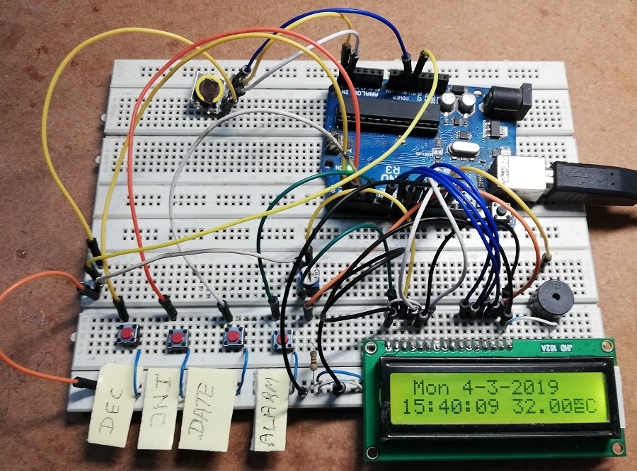
Figure 2: Author Prototype of Arduino Alarm Clock with Time Setting
Software Code:
The software code of the Arduino alarm clock with time setting is written in Arduino programming language and compiled using Arduino IDE. Here, we had used a different library, so before using this code upload this header file to the library folder of Arduino.
#include <DS3231.h>, For date, time, and temperature. Download DS3231.h
#include <Wire.h>, For I2C communication.
#include <LiquidCrystal.h>, For 16×2 liquid crystal display. Download LiquidCrystal.h
#include <Button.h>, For push-to-on button, Download Button.h
Download the library file and code and upload the code to your Arduino board without commenting date and timeline. Must define date and time as shown below.
|
1 2 |
rtc.setTime (5, 33, 00); //Here 5 represents hours, 33 represents minutes and 00 represents seconds rtc.setDate(7, 3, 2019); //Here, 7 represents day, 3 represents months and 2019 represents years. |
Again, upload the entire code with comments on setTime and setDate.
|
1 2 |
//rtc.setTime (5, 33, 00); //rtc.setDate(7, 3, 2019); |
Working off the clock.
- Connect all the components as shown in the circuit diagram.
- Upload the code without comment set date and set timeline.
- Again, upload the code with comments on these two lines.
Date and time setup
- Press the switch SW2 (DATE), the day will start to blink.
- Now, press the switch DEC or INC. (SW1 or SW2) according to your requirement, and then again press the DATE Switch (SW2).
- Now, the month starts to blink. Here also press the INC or DEC switch for a set month and then again press the DATE switch (SW2).
- Do the same process until you set the date and time.
- After setting the date and time it will display the message “SET DATE FINISHED” and “SET TIME FINISHED”
Alarm Time Setup
- Press the switch SW1 (ALARM), a message will display “SET Alarm” with the time and duration of the alarm.
- Now press the INC or DEC switch to set the alarm time (time is in 24-hour format), followed by the alarm switch.
- You can also adjust the duration of the alarm by pressing INC or DEC button, by default alarm duration is of 5 minutes.
- After setting alarm time press the Alarm switch, it will display the message “Set Alarm finished with a time of alarm”.
|
1 2 3 4 5 6 7 8 9 10 11 12 13 14 15 16 17 18 19 20 21 22 23 24 25 26 27 28 29 30 31 32 33 34 35 36 37 38 39 40 41 42 43 44 45 46 47 48 49 50 51 52 53 54 55 56 57 58 59 60 61 62 63 64 65 66 67 68 69 70 71 72 73 74 75 76 77 78 79 80 81 82 83 84 85 86 87 88 89 90 91 92 93 94 95 96 97 98 99 100 101 102 103 104 105 106 107 108 109 110 111 112 113 114 115 116 117 118 119 120 121 122 123 124 125 126 127 128 129 130 131 132 133 134 135 136 137 138 139 140 141 142 143 144 145 146 147 148 149 150 151 152 153 154 155 156 157 158 159 160 161 162 163 164 165 166 167 168 169 170 171 172 173 174 175 176 177 178 179 180 181 182 183 184 185 186 187 188 189 190 191 192 193 194 195 196 197 198 199 200 201 202 203 204 205 206 207 208 209 210 211 212 213 214 215 216 217 218 219 220 221 222 223 224 225 226 227 228 229 230 231 232 233 234 235 236 237 238 239 240 241 242 243 244 245 246 247 248 249 250 251 252 253 254 255 256 257 258 259 260 261 262 263 264 265 266 267 268 269 270 271 272 273 274 275 276 277 278 279 280 281 282 283 284 285 286 287 288 289 290 291 292 293 294 295 296 297 298 299 300 301 302 303 304 305 306 307 308 309 310 311 312 313 314 315 316 317 318 319 320 321 322 323 324 325 326 327 328 329 330 331 332 333 334 335 336 337 338 339 340 341 342 343 |
#include <DS3231.h> #include <Wire.h> #include <LiquidCrystal.h> #include <Button.h> //Pin assignment for button and int DN_PIN = 2; //Down Button int UP_PIN = 3; //Up Button int SET_PIN = 4; //Setup Button int ALR_PIN = 5 ; //Setup Button #define PULLUP true //internal Pull Up #define INVERT true #define DEBOUNCE_MS 20 #define REPEAT_FIRST 500 #define REPEAT_INCR 100 //Declare push buttons Button btnUP(UP_PIN, PULLUP, INVERT, DEBOUNCE_MS); Button btnDN(DN_PIN, PULLUP, INVERT, DEBOUNCE_MS); Button btnSET(SET_PIN, PULLUP, INVERT, DEBOUNCE_MS); Button btnALR(ALR_PIN, PULLUP, INVERT, DEBOUNCE_MS); enum {WAIT, INCR, DECR}; uint8_t STATE; int count; int lastCount = -1; unsigned long rpt = REPEAT_FIRST; LiquidCrystal lcd(12, 11, 10, 9, 8, 7); DS3231 rtc(SDA, SCL); //RTC3231 connected pin Time t; uint32_t targetTime = 0; uint8_t conv2d(const char* p) { uint8_t v = 0; if ('0' <= *p && *p <= '9') v = *p - '0'; return 10 * v + *++p - '0';} uint8_t hh = 0, mm = 0, ss = 0, dd = 0, bb = 0;//initialize date and time to zero int yy = 0; String Day = " "; uint8_t alarmHH = 9, alarmMM = 30; int alarmLONG = 5; uint8_t setMode = 0, setAlarm = 0, alarmMode=0; void setup() { pinMode (13, OUTPUT); lcd.begin(16,2); rtc.begin(); lcd.setCursor (0,0); lcd.print(F(" Digital Clock ")); lcd.setCursor (0,1); lcd.print(F("With Alarm")); delay (2000); lcd.clear(); //rtc.setTime (15, 30, 00); // set time in format of HH:MM:SS in 24 hour format //rtc.setDate(4, 3, 2019); // Set the date in format of DD:MM:YY } void loop() { t = rtc.getTime(); Day = rtc.getDOWStr(1); if (setMode == 0) { hh = t.hour,DEC; mm = t.min,DEC; ss = t.sec,DEC; dd = t.date,DEC; bb = t.mon,DEC; yy = t.year,DEC; } if (setAlarm <2) { lcd.setCursor(1,0); if(setMode==0) lcd.print(Day); else { lcd.print(F("SET")); } lcd.print(F(" ")); lcd.print(dd); lcd.print(F("-")); lcd.print(bb); lcd.print(F("-")); lcd.print(yy); lcd.print(F(" ")); lcd.setCursor(0,1); if (hh<10) { lcd.print(F("0")); } lcd.print(hh); lcd.print(F(":")); if (mm<10) { lcd.print(F("0")); } lcd.print(mm); lcd.print(F(":")); if (ss<10){ lcd.print(F("0"));} lcd.print(ss); lcd.print(F(" ")); lcd.print(rtc.getTemp()); lcd.print((char)0); lcd.print(F("C")); lcd.print(F(" ")); } setupClock(); Alarm (alarmHH, alarmMM, alarmLONG); if (setAlarm <2 && setMode != 0) { delay (100); } if (setAlarm <2 && setMode == 1) { lcd.setCursor(5,0); lcd.print(F(" ")); delay(100); } if (setAlarm <2 && setMode == 2 && bb>9) { lcd.setCursor(8,0); lcd.print(F(" ")); delay(100); } if (setAlarm <2 && setMode == 2 && bb<=9) { lcd.setCursor(8,0); lcd.print(F(" ")); delay(100); } if (setAlarm <2 && setMode == 3 && bb>9) { lcd.setCursor(11,0); lcd.print(F(" ")); delay(100); } if (setAlarm <2 && setMode == 3 && bb<=9) { lcd.setCursor(10,0); lcd.print(F(" ")); delay(100); } if (setAlarm <2 && setMode == 4) { lcd.setCursor(0,1); lcd.print(F(" ")); delay(100); } if (setAlarm <2 && setMode == 5) { lcd.setCursor(3,1); lcd.print(F(" ")); delay(100); } if (setAlarm <2 && setMode == 6) { lcd.setCursor(6,1); lcd.print(F(" ")); delay(100); } if (setMode == 0 && setAlarm != 0 && setAlarm != 1) { delay (100); } if (setMode == 0 && setAlarm == 2) { lcd.setCursor(0,1); lcd.print(F(" ")); delay(100); } if (setMode == 0 && setAlarm == 3) { lcd.setCursor(3,1); lcd.print(F(" ")); delay(100); } if (setMode == 0 && setAlarm == 4 && alarmLONG >9) { lcd.setCursor(12,1); lcd.print(F(" ")); delay(100); } if (setMode == 0 && setAlarm == 4 && alarmLONG <10) { lcd.setCursor(12,1); lcd.print(F(" ")); delay(100); } Serial.print (setMode); Serial.print (" "); Serial.println (setAlarm); } void setupClock (void) { //read the buttons btnUP.read(); btnDN.read(); btnSET.read(); btnALR.read(); if (setMode == 7) { lcd.setCursor (0,0); lcd.print (F("Date is set")); lcd.setCursor (0,1); lcd.print (F("Time is set")); delay (1000); rtc.setTime (hh, mm, ss); rtc.setDate (dd, bb, yy); lcd.clear(); setMode = 0; } if (setAlarm == 5) { lcd.setCursor (0,0); lcd.print (F("Alarm is set")); lcd.setCursor (0,1); lcd.print (F("Alarm at : ")); lcd.print (alarmHH); lcd.print (F(":")); lcd.print (alarmMM); delay (1000); lcd.clear(); setAlarm=0; alarmMode=1; } if (setAlarm >0) { alarmMode=0; } switch (STATE) { case WAIT: if (btnSET.wasPressed()) { setMode = setMode+1; } if (btnALR.wasPressed()) { setAlarm = setAlarm+1; } if (btnUP.wasPressed()) STATE = INCR; else if (btnDN.wasPressed()) STATE = DECR; else if (btnUP.wasReleased()) rpt = REPEAT_FIRST; else if (btnDN.wasReleased()) rpt = REPEAT_FIRST; else if (btnUP.pressedFor(rpt)) { rpt += REPEAT_INCR; STATE = INCR; } else if (btnDN.pressedFor(rpt)) { rpt += REPEAT_INCR; STATE = DECR; } break; case INCR: if (setAlarm<2 && setMode==1 && dd<31)dd=dd+1; if (setAlarm<2 && setMode==2 && bb<12)bb=bb+1; if (setAlarm<2 && setMode==3 && yy<2050)yy=yy+1; if (setAlarm<2 && setMode==4 && hh<23)hh=hh+1; if (setAlarm<2 && setMode==5 && mm<59)mm=mm+1; if (setAlarm<2 && setMode==6 && ss<59)ss=ss+1; if (setMode==0 && setAlarm==2 && alarmHH<23)alarmHH=alarmHH+1; if (setMode==0 && setAlarm==3 && alarmMM<59)alarmMM=alarmMM+1; if (setMode==0 && setAlarm==4 && alarmLONG<59)alarmLONG=alarmLONG+1; STATE = WAIT; break; case DECR: if (setAlarm<2 && setMode==1 && dd>0)dd=dd-1; if (setAlarm<2 && setMode==2 && bb>0)bb=bb-1; if (setAlarm<2 && setMode==3 && yy>2000)yy=yy-1; if (setAlarm<2 && setMode==4 && hh>0)hh=hh-1; if (setAlarm<2 && setMode==5 && mm>0)mm=mm-1; if (setAlarm<2 && setMode==6 && ss>0)ss=ss-1; if (setMode==0 && setAlarm==2 && alarmHH>0)alarmHH=alarmHH-1; if (setMode==0 && setAlarm==3 && alarmMM>0)alarmMM=alarmMM-1; if (setMode==0 && setAlarm==4 && alarmLONG>0)alarmLONG=alarmLONG-1; STATE = WAIT; break; } } void Alarm (uint8_t alarmHH, uint8_t alarmMM,int alarmLONG) { if (alarmMode==1 && hh == alarmHH && (mm - alarmMM >= 0 ) && (mm - alarmMM <= alarmLONG )) { tone (13, 1200); btnALR.read(); if (btnALR.wasPressed()) { alarmMode = 0; } } else { noTone (13); } if (setMode == 0 && setAlarm !=0 && setAlarm !=1) { lcd.setCursor (1,0); lcd.print(F(" Set Alarm ")); lcd.setCursor (0,1); if(alarmHH<10) { lcd.print(F("0")); } lcd.print (alarmHH); lcd.print(F(":")); if(alarmMM<10) { lcd.print(F("0")); } lcd.print (alarmMM); lcd.print(F(" Long:")); lcd.print (alarmLONG); lcd.print(F("mnt ")); } } |
Hello dear
I have an error In this line:
DS3231 rtc(SDA, SCL);
and not verify or upload to Arduino
.
.
.
Arduino UNO R3
LCD 1602 I2C
Please help me…
Hi babak, code is tested and verified please check if you have install all the library specially #include.
And also check if you have install multiple library.
Hello.
I always get the following error message when copying:
no matching function for call to Button: ‘Button (int &, bool, bool, int)’.
What am I doing wrong? I am not a programmer.
VlG Enrico
Hi enrico, first you have to add button.h library to your Arduino IDE.
For that download button.h library and then add to your Arduino IDE.
This will solve the error.
Hi there,
Thanks for the hint. But there are several “button liberys” in the library management. What exactly is it? Perhaps you can tell me the name of the library in question, or what it is labeled. Possibly the name of the programmer.
best regards, Enrico
Hi, please go through the software section of this article, there you will find all the required libraries. Please download the required one and add it to your Arduino IDE.
Hello my friend
I have now integrated your “bottom.master” library about 100 times.
Nevertheless, the red error bar in line 21 remains when compiling and the following error message is displayed: “no matching function for call to ‘Button: Button (int &, Bool, Bool, int). I’m slowly not sure what to do. Greetings,” Enrico
There is no code error.
Possible regions for error messages are
1. Either you have installed another button library
2. Or you had been installed the library in a different folder.
Its possible to add lcd i2c to the code for more simple wire?
Thanks
Hi, you can use an I2C LCD but before that, you have to change the LCD library to the I2C LCD library.
Hi..
How to add more (multiple) alarm based on days of week ?
Thanks,
Hello,
Could we set more than one alarm in this code?
do we really need the set time, month, and date buttons?
Hi,
yes we do need if you wish to setup date and time externally (without code).
I have exactly the same problem, did you manage to fix it?
What type of problem you had faced, please elaborate.
Could I connect this circuit and add the wake up by light features to it sincethey both are connected to PWM pin 9
When I run the code in the simulation it jumps straight to the time settings in addition it does not show the day on the screen