We are getting about how to make the digital clocks more accurate and precise even at varying parameters like temperature and humidity. Generally, in the market, if we go for buying the RTC module we will find the DS1307 module more simply. As DS1307 module is more prone to external temperature variation because it uses an external crystal oscillator circuit as a result the accuracy of the timekeeping changes. While designing a LED board for my college kec.edu.np, I suffered from a time accuracy problem. After a few days, time starts to vary from the original one. Thus, I decided to use a better RTC module that has an internal clock oscillator and I found the DS3132 Module.
|
Table 1: Major Difference Between DS1307 and DS3231 |
|||
| S.N. | DS1307 | S.N. | DS3231 |
| 1. | External Oscillator Clock Circuit | 1. | External Oscillator Clock Circuit |
| 2. | More prone to external temperature variation | 3. | External Temperature variation doesn’t affect much |
| 4. | Time Variation of about 5min / month | 2. | Time variation of about 2 min. / year |
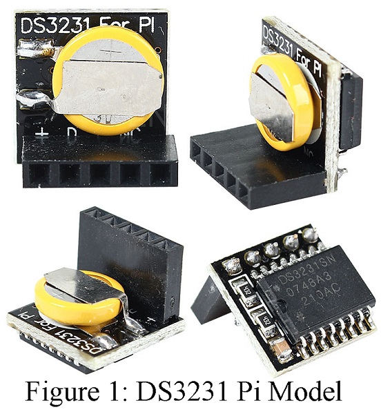
Due to the above reasons, DS3231 is superior to DS1207. The module I have used for making Arduino digital clock using is shown in figure 1. This module is designed for raspberry PI but also can be used with Arduino. In this tutorial, I am going to show how to interface the DS3231 module with Arduino.
Checkout other clock and timer circuits posted on bestengineeringprojects.com
Circuit Description: of Arduino Digital Clock using DS3231 Pi Module
The circuit of the Arduino digital clock using DS3231 shown in figure 2 is designed using very few components i.e. Arduino Uno Board, 16×2 LCD Module, and a DS3231 RTC module.
DS3231 uses SDA (Data Pin) and SCL (Clock Pin) only because of the I2C protocol. This module is designed to communicate using the I2C protocol. So, at first, find the SDA and SCL pin of your Arduino uno or compatible board. If you are using Arduino uno board pin A4 and A5 is SDA and SCL pin respectively. Similarly, if you are using Arduino mega pins 20 and 21 are SDA and SCL respectively.
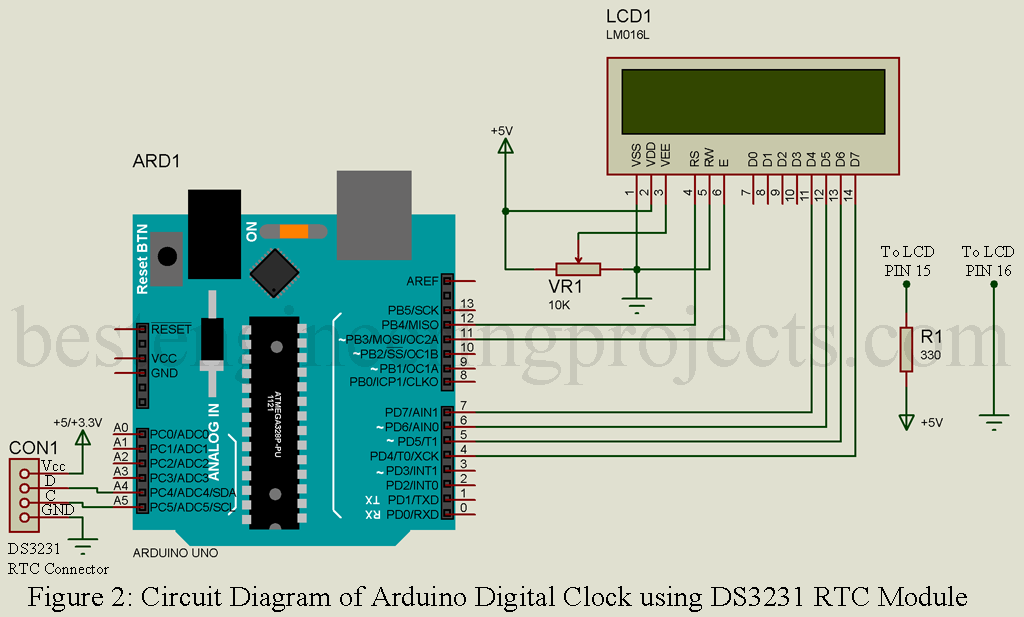
So, connect the SDA or D pin of your RTC module to the SDA pin and the SCL or C pin to the SCL pin of your Arduino board. The Vcc pin of the RTC module can be connected to either +5V or +3.3V of your Arduino and the GND pin to the Ground (GND) pin of your Arduino.
Now, let’s talk about the LCD connection. For easy and better understanding I summarized the connection diagram in the bullet.
- Pin 1 (Vss) of LCD to GND pin of Arduino
- Pin 2 (Vcc) of LCD to +5V pin of Arduino
- Pin 3 (VEE) of LCD to the wiper of 10K variable resistor as shown in the circuit diagram.
- Pin 4 (RS) of LCD to digital pin D12 of Arduino
- Pin 5 (R/W) of LCD to GND pin of Arduino
- Pin 6 (E) of LCD to digital pin D11 of Arduino
- Pin 7, 8, 9, and 10 (D0, D1, D2, and D3) were left unconnected.
- Pin 11 (D4) of LCD to digital pin D7 of Arduino
- Pin 12 (D5) of LCD to digital pin D6 of Arduino
- Pin 13 (D6) of LCD to digital pin D5 of Arduino
- Pin 14 (D7) of LCD to digital pin D4 of Arduino
- Pin 15 (LED+) of LCD to +5V through current limiting resistor 330-ohm.
- Pin 16 (LED-) of LCD to GND pin of Arduino
The connection of the hardware part is completed not let’s talk about the software part.
Software Code :
Software code for Arduino digital clock using DS3231 Pi module is written in Arduino programming language and compiled using Arduino IDE. Download the code from the below, and open it on your IDE.
|
1 2 3 4 5 6 7 8 9 10 11 12 13 14 15 16 17 18 19 20 21 22 23 24 25 26 27 28 29 30 31 32 33 34 35 36 37 38 39 40 41 42 43 44 45 46 47 48 49 50 51 52 53 54 55 56 57 58 59 60 61 62 63 64 65 66 67 68 69 70 71 72 73 74 75 76 77 78 79 80 81 82 83 84 85 86 87 88 89 90 91 92 93 94 95 96 97 98 99 100 101 102 103 104 105 106 107 108 109 110 111 112 113 114 115 116 117 118 119 120 121 122 123 124 125 126 127 128 129 130 131 132 133 134 135 136 137 138 139 140 141 142 143 144 145 146 147 148 149 150 151 152 153 154 155 156 157 158 |
#include "Wire.h" #include <LiquidCrystal.h> LiquidCrystal lcd(12, 11, 7, 6, 5, 4); #define DS3231_I2C_ADDRESS 0x68 // Convert normal decimal numbers to binary coded decimal byte decToBcd(byte val) { return( (val/10*16) + (val%10) ); } // Convert binary coded decimal to normal decimal numbers byte bcdToDec(byte val) { return( (val/16*10) + (val%16) ); } void setup() { Wire.begin(); Serial.begin(9600); lcd.begin(16,2); // set the initial time here: // DS3231 seconds, minutes, hours, day, date, month, year //setDS3231time(30,26,23,3,21,8,18); } void setDS3231time(byte second, byte minute, byte hour, byte dayOfWeek, byte dayOfMonth, byte month, byte year) { // sets time and date data to DS3231 Wire.beginTransmission(DS3231_I2C_ADDRESS); Wire.write(0); // set next input to start at the seconds register Wire.write(decToBcd(second)); // set seconds Wire.write(decToBcd(minute)); // set minutes Wire.write(decToBcd(hour)); // set hours Wire.write(decToBcd(dayOfWeek)); // set day of week (1=Sunday, 7=Saturday) Wire.write(decToBcd(dayOfMonth)); // set date (1 to 31) Wire.write(decToBcd(month)); // set month Wire.write(decToBcd(year)); // set year (0 to 99) Wire.endTransmission(); } void readDS3231time(byte *second, byte *minute, byte *hour, byte *dayOfWeek, byte *dayOfMonth, byte *month, byte *year) { Wire.beginTransmission(DS3231_I2C_ADDRESS); Wire.write(0); // set DS3231 register pointer to 00h Wire.endTransmission(); Wire.requestFrom(DS3231_I2C_ADDRESS, 7); // request seven bytes of data from DS3231 starting from register 00h *second = bcdToDec(Wire.read() & 0x7f); *minute = bcdToDec(Wire.read()); *hour = bcdToDec(Wire.read() & 0x3f); *dayOfWeek = bcdToDec(Wire.read()); *dayOfMonth = bcdToDec(Wire.read()); *month = bcdToDec(Wire.read()); *year = bcdToDec(Wire.read()); } void displayTime() { byte second, minute, hour, dayOfWeek, dayOfMonth, month, year; // retrieve data from DS3231 readDS3231time(&second, &minute, &hour, &dayOfWeek, &dayOfMonth, &month, &year); lcd.setCursor(0,0); lcd.print("Time:"); // send it to the serial monitor Serial.print(hour, DEC); lcd.setCursor(6,0); lcd.print(hour); lcd.setCursor(8,0); lcd.print(":"); // convert the byte variable to a decimal number when displayed Serial.print(":"); if (minute<10) { Serial.print("0"); } Serial.print(minute, DEC); Serial.print(":"); lcd.setCursor(9,0); lcd.print(minute); lcd.setCursor(11,0); lcd.print(":"); if (second<10) { Serial.print("0"); } Serial.print(second, DEC); lcd.setCursor(12,0); lcd.print(second); Serial.print(" "); Serial.print(dayOfMonth, DEC); lcd.setCursor(0,1); lcd.print("Date:"); lcd.setCursor(5,1); lcd.print(dayOfMonth); lcd.setCursor(7,1); lcd.print("/"); Serial.print("/"); Serial.print(month, DEC); Serial.print("/"); lcd.setCursor(8,1); lcd.print(month); lcd.setCursor(10,1); lcd.print("/"); Serial.print(year, DEC); lcd.setCursor(11,1); lcd.print(year); Serial.print(" Day of week: "); switch(dayOfWeek){ case 1: Serial.println("Sunday"); lcd.setCursor(13,1); lcd.print("SUN"); break; case 2: Serial.println("Monday"); lcd.setCursor(13,1); lcd.print("MON"); break; case 3: Serial.println("Tuesday"); lcd.setCursor(13,1); lcd.print("TUE"); break; case 4: Serial.println("Wednesday"); lcd.setCursor(13,1); lcd.print("WED"); break; case 5: Serial.println("Thursday"); lcd.setCursor(13,1); lcd.print("THU"); break; case 6: Serial.println("Friday"); lcd.setCursor(13,1); lcd.print("FRI"); break; case 7: Serial.println("Saturday"); lcd.setCursor(13,1); lcd.print("SAT"); break; } } void loop() { displayTime(); // display the real-time clock data on the Serial Monitor, delay(1000); // every second } |
You have to change a few code setups before uploading the code to your Arduino.
- Open the code in your IDE
- Scroll down to the void setup menu, where you see a few lines with comment
|
1 2 3 |
// set the initial time here: // DS3231 seconds, minutes, hours, day, date, month, year //setDS3231time(30,26,23,3,21,8,18); |
- In setDS3231time() line you have to enter the current date and time in a predefined way. Like if you wish to inter 11:30:48Pm, Tuesday, 21st, August 2018 then you have to enter setDS3231time(48,30,23,3,21,8,18); As this is a 24hour clock format you have to use 23 for 11 pm and remove the connecting line from the function setDS3231time() as shown below.
|
1 2 3 |
// set the initial time here: // DS3231 seconds, minutes, hours, day, date, month, year setDS3231time(30,26,23,3,21,8,18); |
- Upload the code to your Arduino uno board. This is done to tell the DS3231 module to start the date and time from the above-set date and time.
- Now, again you have to comment on that time setup line because if you are not doing so every time you interrupt the power supply the date and time it shows will be above the set date and time.
|
1 2 3 |
// set the initial time here: // DS3231 seconds, minutes, hours, day, date, month, year //setDS3231time(30,26,23,3,21,8,18); |
- Again, upload the code with commented setDS3231time();
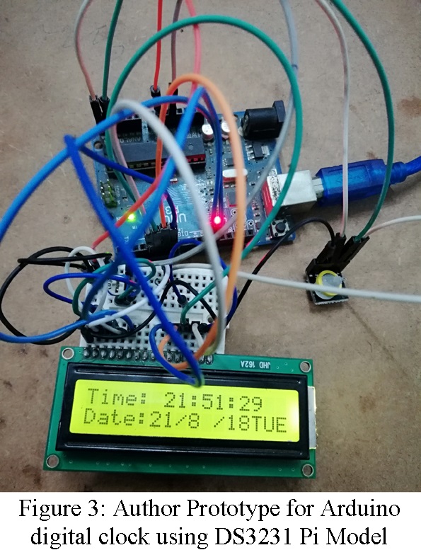
Making video of Arduino Digital clock using DS3231 Pi Model