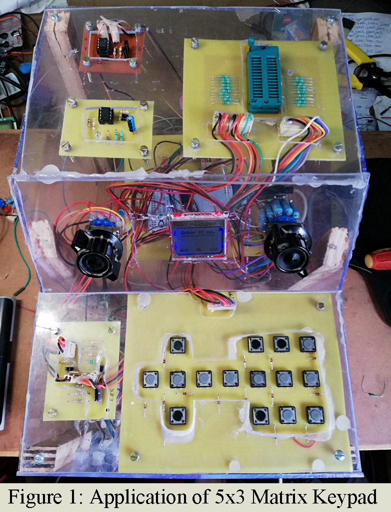
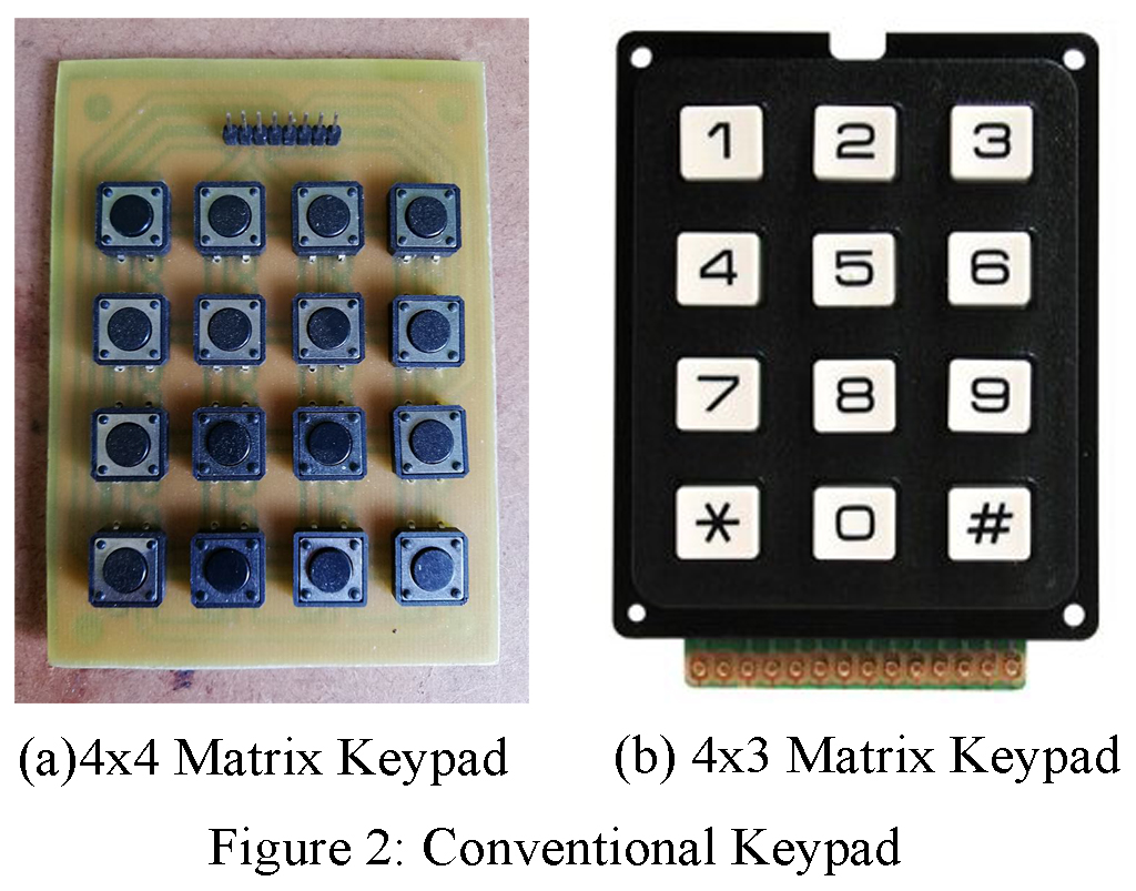
In this tutorial we are going to design a customized DIY 5×3 matrix keypad for arduino using tactile switch and small signal diode 1N4148. Many microcomputer/ Arduino system designs require some type of a keypad as an input device. Some time we required customized key for our own project rather then conventional available matrix keypad (4×4 or 4×3) in market. What if we require the key for other operation like left, right, up, down and ok operation. The outlook of the project may not be sophisticated if we had used conventional keypad. The picture in figure 1 uses own customized key (5×3) for better look and better understanding. Where Figure 2 shown the conventional keypad available in market. You may also like interfacing 4×4 keypad using single line : Interface 4×4 Keypad and ATmega32 with Single Pin
Before going to working principle, we would like to discuss about components used in the project Customized keypad for Arduino
Component Required for DIY 5×3 matrix keypad for arduino
| S.N. | No. of Component | Component Name | Remarks |
| 1. | 15-Piece | Tactile Switch | Selection Switch |
| 2. | 15- Piece | 1N4148 Diode | Elimination unexpected Results |
| 3. | 1-Piece | PCB Board | Approx. size 15×12 Cm |
| 4. | 8-piece | Male Connector | Connector for 5 rows and 3 column |
Purpose of using Matrix Keypad | DIY 5×3 matrix keypad for arduino
If we use tactile switch without matrix principle, the number of input/output (I/O) required is comparatively high. Let, say our system requires 15 different keys then we have to assign 15 different input/output pins for operation if we are using non-matrix principle. But if we use matrix principle we only require approx. half number of pin (say 8).
Thus, from above we conclude that matrix principle basically reduces the number of pins required for keypad operation.
Purpose of using 1N4148 Diode | DIY 5×3 matrix keypad for arduino
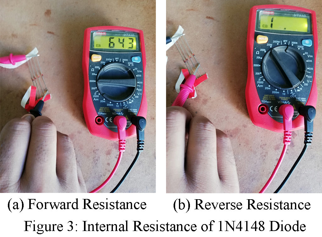
As your cam see that we had used 15 1N4148 (Silicon Switching) diode along with each tactile switch. The purpose of using this diode is to eliminate error in results due to simultaneous multiple pressing of switch. If you measure the forward resistance 1N4148, it would be not more then 700-ohm (preciously saying 643-ohm) and the reverse resistance would be infinity as shown in figure 3. So, it works also as pull-down resistor.
How does matrix keypad work? | DIY 5×3 matrix keypad for arduino
Let us suppose, we are using 5×3 matrix keypad i.e. it has 5 rows and 3 columns. While the circuit taking an input from only one column out of 3 at a time. The column to be read is connected to different logic voltage then row pins (say logic 0 volt).
Now, lets talk about state of rows, we can detect the state of rows when the particular key from particular column is pressed. One key of each row is connected to one column i.e. 5 keys from 5 rows is connected to single column and 3 keys of each column is connect to single row as shown in circuit diagram (figure). The controlling circuit scan entire column one after another, in this way all column is scanned and complete the cycle of matrix scan.
The speed of scan is depending upon the clock speed of controller used. An arduino board is capable of scanning the whole matrix keypad thousand of times per second, as it uses clock generator of 16 MHz
Connection Description of DIY 5×3 matrix keypad for arduino
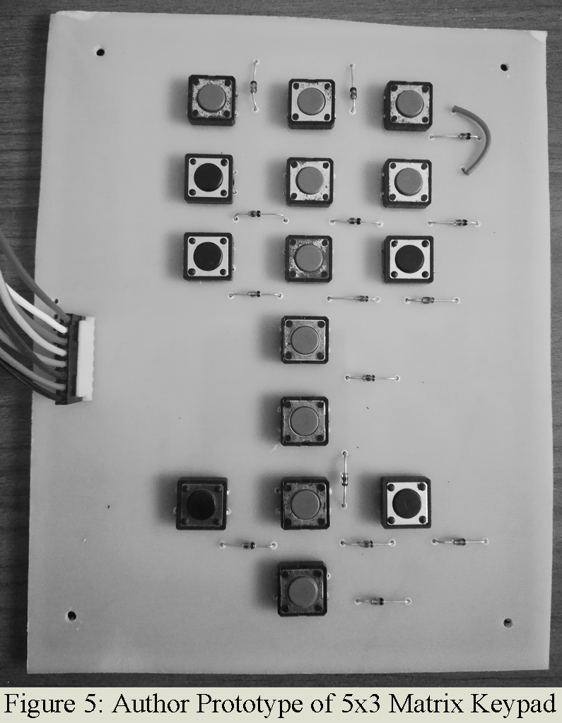
The circuit of DIY customized 5×3 matrix keypad is shown in figure 5 and is designed using few electronics components like tactile switch, 1N4148 diode and male connectors. One pin of each tactile switch is connector in row where other pin of tactile switch is connected to column through diode as shown in circuit diagram. Three switches are arranged in each row where five switches are arranged in each column.

PCB Design
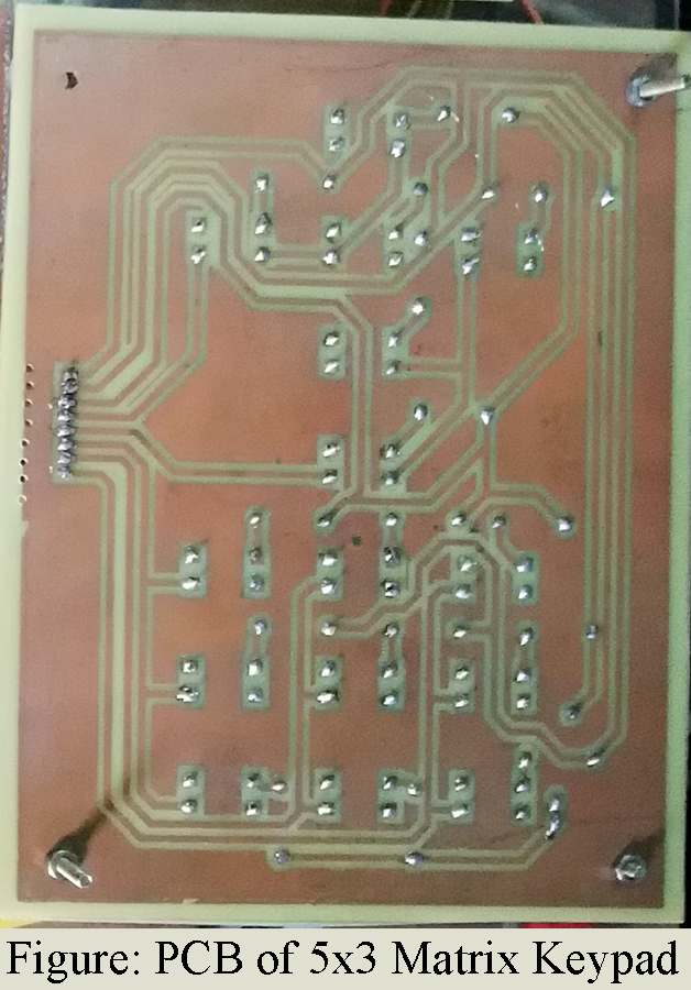
The Solder side PCB and Component side PCB diagram is shown in figure 5 and 6 respectively. Proteous 8.0 is used to design the PCB diagram of () You can also download the PDF file of PCB from the link given below.
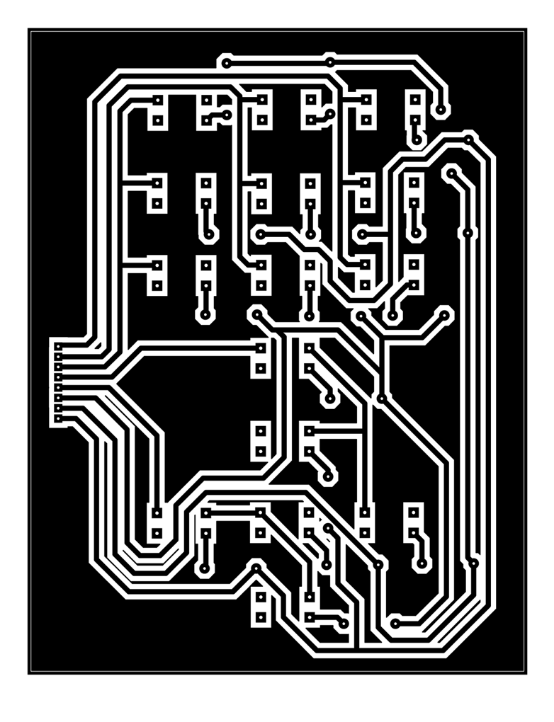 Figure 6: Solder Side PCB of 5×3 Matrix Keypad
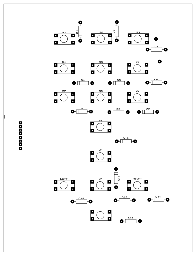 Figure 7: Component Side PCB for 5×3 Matrix keypad
Click here to download the PCB File
We have made the customized library file for the customized PCB you can directly down the library file from the link below.
Click here to download the library file