How to interface the 4×4 keypad and atmega32 with a single pin?
While working with most of the electronic projects, you might have noticed one thing in common; they involve several multiple connections between the components used and the microcontroller. Well, it does seem a necessity too, since doing some hardware work in a certain way is not a piece of cake. Because of this, we are compelled to remove some components or include an additional microcontroller in the project which makes it bulkier and less convenient. To address this problem, we have come up with a solution: interfacing with a single pin! The project we have presented here provides an alternate way of connecting a 4×4 matrix keypad with an ATmega32 AVR microcontroller.
ATmega32 is an 8-bit AVR (Alf and Vegard’s RISC processor, which isn’t an official acronym as per the developers yet it is ordinarily accepted as so) microcontroller with 40 pins among which 32 are I/O ports. These 32 ports are programmable and hence we can easily interface with other devices which makes ATmega32 ample to use in most embedded systems. Unlike digital ICs, it is not a Plug Play device. The programs must be written into the flash memory of Atmega32 using the ‘C’ programming language. ATmega8 and ATmega328p are some of the alternatives to ATmega32 microcontroller. Some of the common applications of the ATmeaga32 microcontroller are a coffee vending machine, temperature control systems, and digital signal processing amongst others.
The keypad is a common component in almost every project to access control of what needs to be done. And for a 4×4 keypad with 16 keys, it occupies eight digital I/O lines of the microcontroller device while interfacing. With the help of this project, we will be able to interface a 4×4 keypad to a microcontroller through a single analog pin. As a result, the loop of wires is reduced and more pins are available for various other multiple purposes.
Circuit Description and Working of Interface 4×4 Keypad and ATmega32 with Single Pin
The connection arrangement between the microcontroller, keypad, and Liquid Crystal Display (LCD) is clearly shown in Fig. 1. The heart of the project is an ATmega32 microcontroller (IC2), around which the whole circuit relies, followed by a step-down transformer X1, 16 pushbutton switches (S1-S16), 16 resistors (R1-R16), a 5V regulator 7805 (IC1), an LCD (LCD1) and a few other discrete components. Like every project, it has three sections: input (keypad), power supply, and output (display).
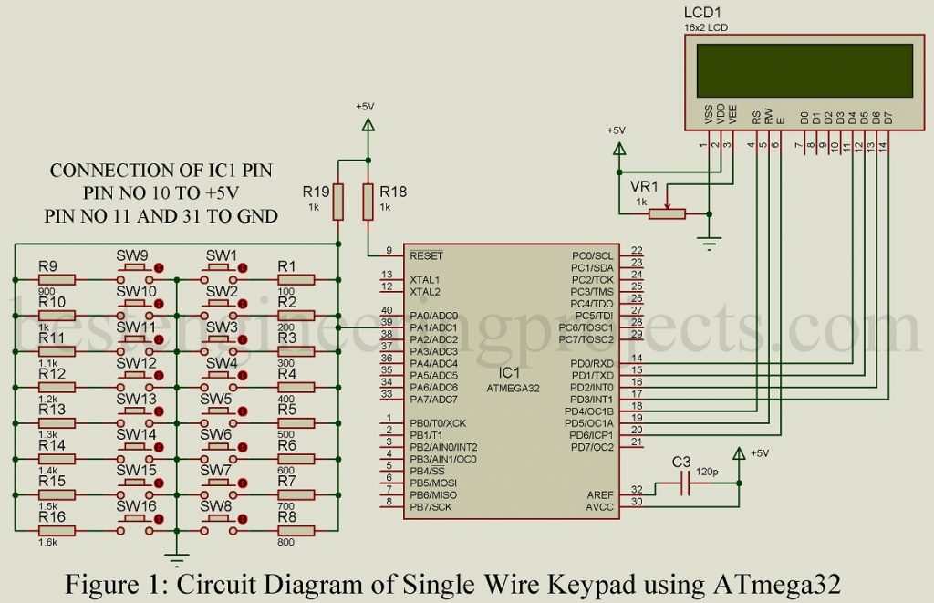
For displaying the input data fed to the microcontroller through the keypad, a Hitachi HD44780-controlled LCD module is used. A 16×2(16-character, 2-line) LCD consists of eight data lines (D0-D7) out of which only four data lines (D4-D7) are used here. A 4-bit data is transmitted two times to complete the data transfer procedure between the microcontroller and the LCD module. Some pins from Port-D of the microcontroller (PD0-PD3) are dedicated to establishing a connection between the IC2 and LCD1 through data lines D4-D7 of LCD1. Similarly, remaining Port-D pins PD4, PD5, and PD6 are linked with register-select (RS), read/write (R/W), and enable (EN) pins of LCD1 respectively.
Keypad | Interface 4×4 Keypad and ATmega32 with Single Pin
A manual keypad with 16 press keys is designed and constructed. It requires 16 pushbutton switches fixed on a PCB in a 4×4 keypad matrix layout. One end of pushbuttons is linked to a common ground whereas the other ends are fused in series along with 16 resistors (R1-R16) each. For clear references, see figure 1.
To identify any particular key pressed by the user, we have implemented the voltage divider concept. Initially, resistor R19 (1-kilo-ohm) is connected across a 5V power supply of the circuit. As soon as the pushbutton switch is pressed, that combination of switch and resistor completes the circuit and forms a voltage divider circuit together with resistor R19. At, pin 39(PA1) or ADC pin (ADC1) of the microcontroller, variable voltage is obtained, the value of which can be calculated from the formulae given below:
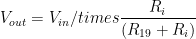
On the right-hand side of this equation, all values are known to us. The input voltage has a constant value of 5V, Ri is the value of the resistor connected in series with the pushbutton pressed and the value R19 is 1 kilo-ohm.
Power Supply Arrangement | Interface 4×4 Keypad and ATmega32 with Single Pin
As required, a secondary transformer (X1) is used to step down the 230V AC mains to a 9V supply. The stepped-down voltage is further rectified by a bridge rectifier module (BR1) and is passed through two filtering capacitors; C1 and C2. It is then regulated using a 7805 regulator IC. The presence of a regulated power supply is confirmed by the glow of LED1.

Thus, a 5V regulated DC supply is connected to the microcontroller and LCD1. Instead of this, we can also opt for a 9V AC mains adaptor to run the circuit.
The power circulates through the circuit when the switch S17 is turned on. In cases, where a transformer is not used, connect S17 directly to a 9V supply.
Software program | Interface 4×4 Keypad and ATmega32 with Single Pin
To make this project functional, we have written the project using the ‘C’ programming language. And, we also need two software tools: AVR Studio 4 and WinAVR to work with the Atmel AVR microcontroller. Both of these software are free and available for download in any browser.
‘C’ program functions
For the ADC module, LCD1, and keypad, dedicated functions written in the ‘C’ program are used. The circuit operation is very simple to understand since all switches are connected to a common point ADC1. The code is written in such a way that the microcontroller checks the input switches through ADC1 periodically. The voltage value at ADC is listed and the corresponding switch number is displayed on the LCD1. It uses the hysteresis approach to detect the ADC value. Depending on that, the pushbutton that has been pressed is found. For the detection procedure, the following functions are used:
| Syntax | Functions |
| Display key on LCD(unsigned long ADC_value) | This function prints the key pressed on the LCD after decoding the ADC value |
| DisplayKeyPressed() | This function executes every 100 msec |
| ReadKey() | This function is used for acquiring ADC value on ADC1 pin |
CLICK HERE TO DOWNLOAD THE SOFTWARE CODE
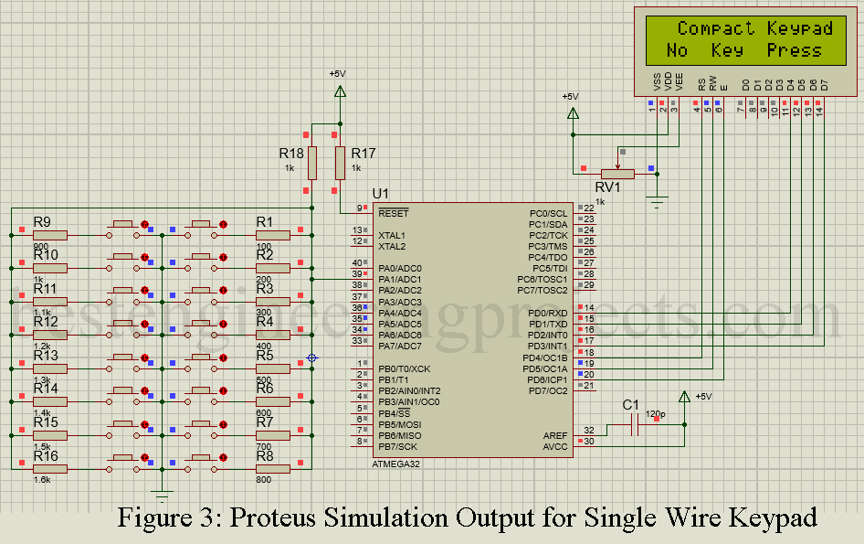
The testing job is the easiest of all. The project is fed with a 9V supply via switch S17 and the LED1 glows to verify the presence of a power supply in the circuit. The initialization process for LCD1 and the microcontroller IC2 takes some time, so we have to wait for a few seconds. Once the setup is ready, you will see the ‘No Key Press’ message on the LCD as in figure 5.
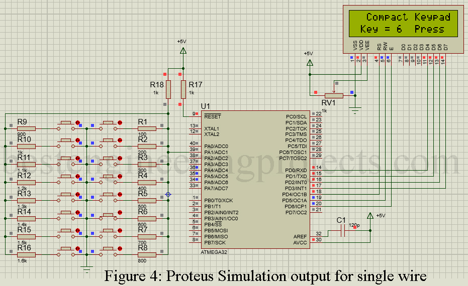
You can adjust the contrast of the LCD module by changing the pre-set value for a clear visual interpretation of the texts on the LCD screen. Further, press switch S1 and see if the voltage level between PIN 39 of the microcontroller and the ground is 0.455V approximately.
PARTS LIST OF INTERFACE 4X4 KEYPAD AND ATMEGA32 WITH SINGLE PIN
| Resistors (all ¼-watt, ± 5% Carbon) |
| R1 = 100 Ω
R2 = 200 Ω R3 = 300 Ω R4 = 400 Ω R5 = 500 Ω R6 = 600 Ω R7 = 700 Ω R8 = 800 Ω R9 = 900 Ω R10, R18, R19 = 1 KΩ R11 = 1.1 KΩ R12 = 1.2 KΩ R13 = 1.3 KΩ R14 = 1.4 KΩ R15 = 1.5 KΩ R16 = 1.6 KΩ R17 = 180 Ω VR1 = 1 KΩ |
| Capacitors |
| C1 = 1000 µF, 35V (Electrolytic Capacitor)
C2 = 10 µF, 16V (Electrolytic Capacitor) C3 = 120 pF (Ceramic Disc) |
| Semiconductors |
| IC1 = ATmega32 (AVR Microcontroller)
IC2 = 7805 (5V series voltage regulator) BR1 = 1A Bridge Rectifier LED1 = 5mm, any color LED |
| Miscellaneous |
| LCD1 = 16×2 Alphanumeric LCD
SW1 – SW16 = Push-to-on Switch X1 = 230V AC Primary to 9V, 250mA Secondary Transformer |