What are the application of op-amp (operational amplifier)?
Op-Amp may perform numerous mathematical operations; hence the name operational amplifier. We here consider some of the applications of Op-Amp.
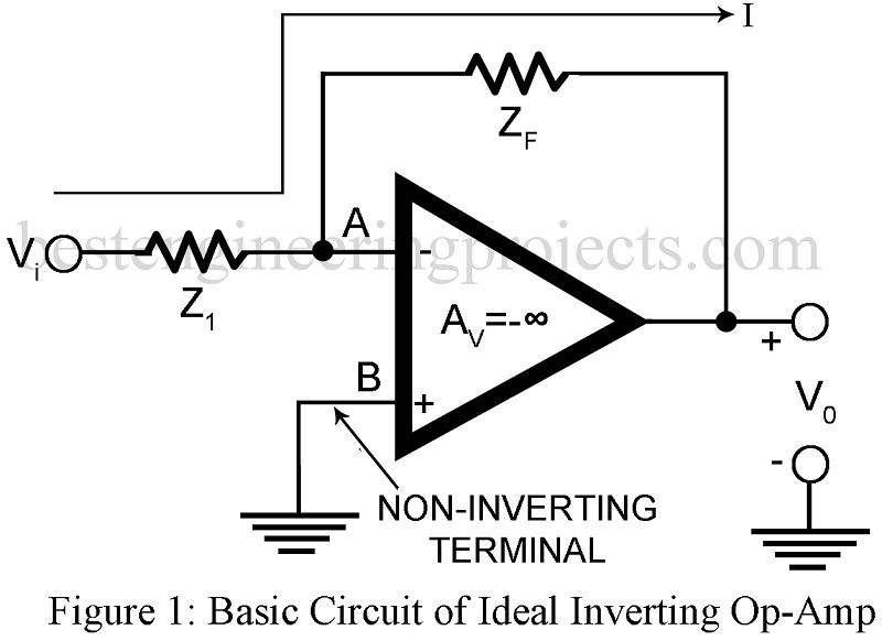
Thus, consider the ideal inverting Op-Amp of figure 1 with voltage shunt feedback through Zf. Equation 1 may be used to secure various operations as analog inverter and paraphase amplifier, scale changer, phase shifter, analog adder, current-to-voltage converter etc.
 …..(1)
Analog Inverter and Paraphase Amplifier:
In Figure 1, Let Z1 = Zf, then AVf = -1 and V0 = -Vi. Thus, the sign of the input signal has simply been changed. Hence such a circuit is called a sign changer or analog inverter. On connecting two such inverting amplifiers in cascade, the output of the second stage exactly equals the signal input in magnitude and is in the same phase. Thus, the outputs of the first stage and the second stage are equal in magnitude and opposite in phase i.e. V02 = -V01. Further R02 = R01. The system thus acts as a paraphase.
Scale Changer
Let Zf = kZ1 where k is a real constant. Then AVf = -k. thus the input has been multiplied by a factor k i.e. scale of the input has been multiplied by factor k. Impedance z and z’ are then chosen as precision resistors.
Phase Shifter
Let Z1 and Zf be equal in magnitude but different in phase angle. Then the inverting Op-Amp shift the phase of the sinusoidal input signal without altering the amplitude. Thus, it becomes possible to obtain any desired phase shift from 0 to 3600.
Analog Adder or Summing Amplifier | Application of Op-amp
Figure 2 gives the circuit of an op-amp as adder or summing amplifier. Here a number of resistors are connected to the input node of the inverting Op-Amp with each resistor returned to a different source.
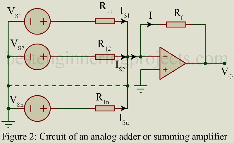
Since a virtual ground exists at the Op-Amp input, we have,
 …..(2)
And,
 ……(3)
……(3)
 ………(4)
The output voltage V0 is the weighted sum of the input signals.
If  say, then
 ……(5)
……(5)
Equation 5 shows that the output voltage V0 is proportional to the sum of the input voltages Vs1, Vs2,……Vsn. Thus, the inverting Op-Amp functions as an analog adder or summing amplifier
The summing operation can, no doubt, be achieved by various other methods. But the circuit of figure 2 has the merit that it may be used to include a very large number of inputs requiring only one additional resistor per input. Further because of the virtual ground, there is little interaction between input sources.
Voltage to Current Converter | Application of op-amp
In a few systems, such as drive for the deflection coil in a TV picture tube, we are required to convert a voltage signal into a proportional current signal. With load impedance floating i.e. with neither end grounded, we may simply use the circuit of figure 2 with Rf replaced by the load impedance Z1 to form an excellent voltage to current converter. For a single input Vs(t), the current in the load impedance Z1 is given by,
 …….(6)
Equation 6 shows that the output current I1 is independent of Z1 because of the virtual ground at the input of the Op-Amp. Further this load current I1 also flows through the signal source. Hence it is necessary that signal source be capable of providing this load current I1.
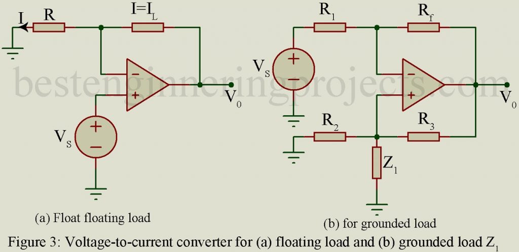
Figure 3 shows an alternative circuit of voltage-to-current generator for a floating load. In this circuit, the source Vs is placed in the non-inverting input terminal. The circuit has the merit that is requires very little current from the signal source due to very large input resistance seen by the non-inverting terminal.
Figure 3(b) shows the circuit of voltage-to-current converter for a grounded load. It may be shown that if 
Then,  ……(7)
……(7)
Thus, the load current I1 is proportional to source voltage Vs and is independent of load impedance Z1.
Current to Voltage Converter | Application of Op-amp
Photo diode and photo multiplier tubes provide output current proportional to the light flux but independent of the load impedance. Figure 4 shows an Op-amp which works as current to voltage converter. Current source Is with shunt source resistance Rs is applied at the inverting terminal of the Op-Amp. Virtual ground at the input makes the current in Rs to be zero and hence the full current Is flows through the feedback resistor Rf resulting in the output voltage V0 = -IsRf.
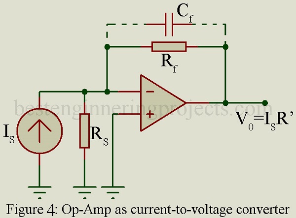
However, in this circuit, the lower limit on current measurement is set by the bias current of the inverting input. Often a capacitor Cf is placed in shunt with Rf to reduce the high frequency noise.
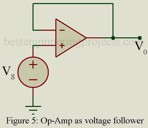
DC Voltage Follower
Figure 5 gives an Op-Amp working as a voltage follower. Since the two-input voltage are tied together, V0 = Vs and thus the output voltage V0 follows the input voltage Vs. Carefully designed voltage follower Op-Amp chips are capable of providing extremely high input resistance (> 104 MΩ), very low input current (< 3 nA) and very low output resistance (few Ω).
Op-Amp Integrator | Application of Op-Amp
In the inverting Op-Amp of figure, if we let Z1 = R and Zf be represented by a capacitor C as shown in figure 6, then the Op-Amp becomes an operational integrator. Figure 6(b) gives the equivalent circuit with virtual ground.
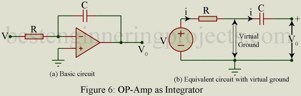
It may be shown that the circuit of figure 6(a) performs the mathematical function of integration. Further the input voltage need not be sinusoidal and hence in figure 6(a), the input voltage has been represented by lower case letter v. Now since there is present virtual ground at input terminals of Op-Amp as shown in Figure 6(b), the time varying current i which flows through R is given by,
 ……(8)
……(8)
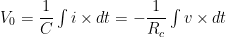
The same current i flows through the capacitor C. Hence the output voltage V0 is given by,
 …..(9)
Equation 9 shows that the Op-Amp provides an output voltage Vo which is proportional to the integral of the input voltage V.
For constant input voltage, v = V and then the output voltage is given by  . Thus, the output voltage is a ramp function. Hence this integrator circuit may be conveniently used as an excellent voltage sweep generator.
Op-Amp Differentiator | Application of Op-Amp
In the inverting Op-Amp of figure, if we let Zf = R and Z1 be represented by a capacitor C as shown in figure 7(a), then the Op-Amp becomes an operational differentiator. Figure 7(b) gives the equivalent circuit with virtual ground.
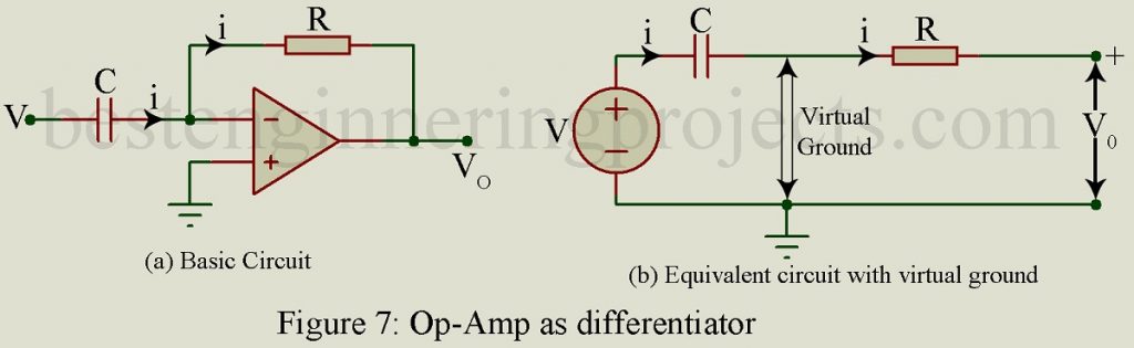
It may be shown that the circuit of figure 7(a) performs the mathematical operation of differentiation. Further as in the case of integrator, the input voltage need not be sinusoidal and hence in figure 7, the input voltage is shown by the lower-case letter v. Because of the presence of virtual ground at the input terminals of the Op-Amp as shown in figure 7(b), the time varying current i that flows through C is given by,
 …..(10)
The same current i flows through the resistor R. hence the output voltage vo is given by,
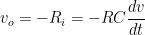 …..(11)
Equation 11 shows that the Op-Amp provides an output voltage vo which is proportional to the time derivative of the input voltage v.
Let the input voltage be sinusoidal and be given by,
 …..(12)
Then the output voltage is given by,
 …..(13)
Thus, the magnitude of the output voltage increases linearly with the frequency  and the differentiator circuit has high voltage gain at high frequencies. Hence the high frequency components of noise get greatly amplified and the resulting noise output may greatly reduce the signal/noise power ratio in the differentiator output.