A small, cheap, reliable device is making its way into technology. We call it the ESP8266 Wi-Fi module which has reached almost everywhere. However, the fact that its related information on datasheets and documents are provided in the Chinese language; Mandarin makes the implementation process complicated. As a solution, people have opted for the ESP8266 community forum which discusses issues users of this module tackle while programming this module.
This small wifi-chip ESP8266 constitutes a built-in 32-bit low-power CPU. The chip itself can be employed as a stand-alone device or can be used along with a microcontroller to resolve wifi networks and carry out software applications. The COM port in this module ensures the connection of the inbuilt-AT Command Firmware with the microcontroller.
Circuit Description of Arduino and ESP8266 Based Web Server
The circuit diagram of Arduino and ESP8622 Based Web Server is shown in figure 1. A power supply of 3.3 volts is provided to the module. To establish the connection between the PC and the COM port of the module, a connector; CON2 is used. The USB-to-serial converter helps to feed the program to the module. In cases where the PC has an inbuilt COM port, the converter can be avoided.
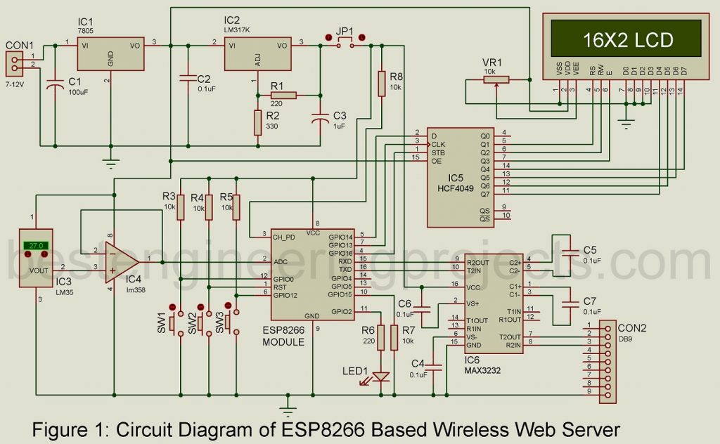
There are all-together 16 pins on the wifi module ESP8266. The 3.3volt supply is provided at pin 1 (RESET) through resistor R5 and for manual reset push-button, S2 is attached. Similarly, another pin 12 (Programming mode pin; GPIO0) is connected to 3.3V through resistor R3, and a switch S1 is placed to switch on the programming mode. With R8, pin 3 (CH_PD) is also clamped to the supply 3.3V.
It is a must to measure the voltage level in the sensor or a battery and for that purpose, the chip uses a general-purpose 10-bit resolution ADC (pin 2). However, during the transmission process through the chip, the ADC cannot measure accurate voltage levels and it is better if we avoid such situations.
Over-voltage running through the circuit is one of the worst scenarios we can think of, it will ruin the circuit completely and to eliminate that possibility, a snap-back circuit is connected in between the pad and the ground protecting all digital input/output pins. Though the snap-back circuit has a 6V capacity, it can hold a maximum voltage level of 5.8 V. The snap-back circuit also protects from ESD. Diodes are responsible for the protection of output devices from reverse voltage. And, in the same way, LED1 is connected to pin 11 (GPIO2), Pin 6 (GPIO12) is connected to 3.3V through resistor R4 and it constitutes a push-button (S3) for debugging purposes.
Since the output pin arrangement pattern differs from suppliers, the Wifi-module doesn’t have a particular PCB design.
Here we designed the PCB as per our requirement. The project is designed to monitor the room temperature using a temperature sensor LM35 and a control LED using the web browser. This temperature sensor has a sensitivity of 10 millivolt/1°C. This is just one simple reference of how to utilize the module in practical life. You are free to implement in multiple ways possible.
The module has unlimited applications; it can be used for home automation, industrial wireless control, IP cameras, mesh networks, sensor networks, smart power plugs, baby monitors, wearable electronics, security ID tags, position system beacons, location-aware devices, and many more.
Software Code of Arduino and ESP8266 based Web Server
Arduino is used just to feed the program to the module. And so, Arduino IDE is responsible for compiling and loading programs. A suitable plugin has been developed by the ESP8266 community which makes it easy to use with Arduino IDE. It supports three varieties of WiFi boards; generic ESP8266 board, node MCU ESP8266 board, and OLIMEX ESP8266 development board.
The procedure of Installing ESP8266 Addon in Arduino IDE (1.8.5 Version).
- At first download the latest version of Arduino IDE from Arduino.cc and install it on your system.
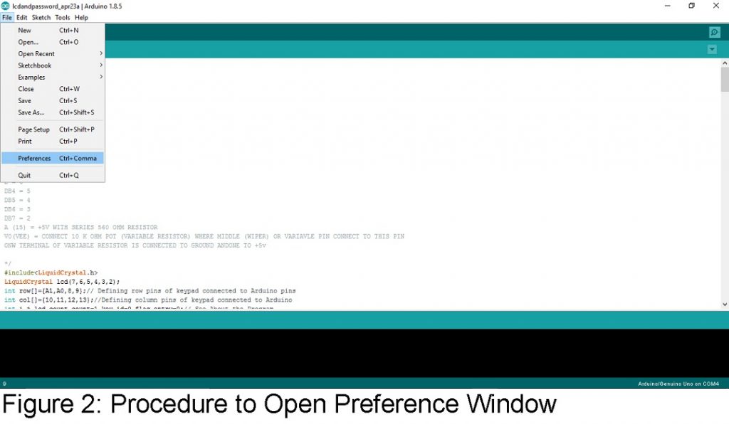
- Lunch Arduino IDE and open File from the menu and then click on preferences as shown in figure 2.
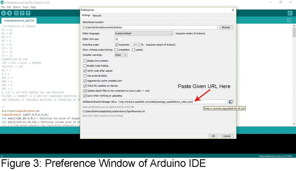
- A Preference window will pup-up. In that choose Additional Boards Manager URLs and enter the given link and click ok as shown in figure 3. http://Arduino.esp8266.com/stable/package_esp8266com_index.json.
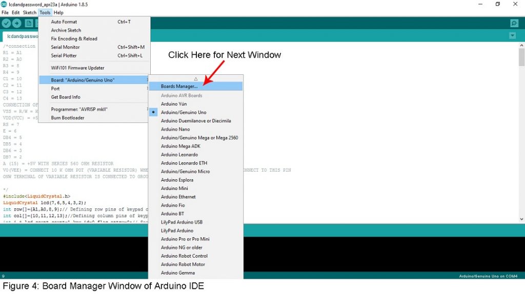
- Now click on “Tools” from the menu and then ‘Board: “Arduino/Genuino Uno”’. After that select “Boards Manager..” as shown in figure 4.
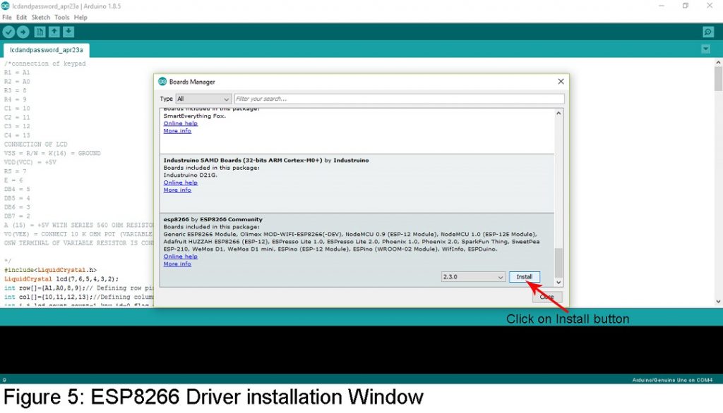
- Now scroll down and find “esp8266 by ESP8266 Community” and highlight it by clicking on it and then Install as shown in figure 5. Which might take several minutes according to your internet speed.
Now let’s focus on software parts, the program is easy to understand.
There are different sections in the program responsible for different tasks as mentioned below:
| Routine | Function |
| setup() | Hardware Initializes by configuring the GPIO2 pin as output and GPIO12 as input. |
| setupWiFi() | does the work of configuring the wireless section. |
| loop() | assigned to handle requests from the client. |
| Function size_t sendProgmem(WiFiClient client, const char progmem[], size_t size), | Sending the requested data to the client |
| IN[ ] | Web page (Figure 6) |
A free software hexy is used to create an array from files. It is important to remove the image extension(.jpg) while creating the array for decoding purposes.

Some routines are assigned to change, store SSID and passwords. When the Wifi setup of the ESP8266 module is completed, an 8-bit serial shift to parallel-shift register program using HCF4094 is used for LCD interface.
A USB-to-serial converter software driver is installed and the loop backtest is performed.
Go to Tool in the menu section and then click on Board: “Arduino/Genuino Uno”. Scroll down and select Generic ESP8266 Board Module. Once it accepts the board, feed the program using the Upload button. Before doing so, connect the COM port (CON2) of the mainboard to your PC through the serial-to-USB converter and select as well as note down the emulating virtual COM port number to ensure the program is loaded successfully to the module.
To activate the program mode, hold the Program button S1 (GPIO0) down and at the same time, press the Reset button (S2) down. Then Release Reset and after that release S1 (GPIO0) button. Now ESP8266 will work in program mode. When you click on the Upload button, the compilation process begins and a bin file is generated which is then loaded to the Wifi module.
Then turn off the power supply to the mainboard and then power on the Wifi module. From the PC, open HyperTerminal with the baud rate 115200 and select COM port. And, Hold switch S3 down and power on the mainboard. Now, let go of the switch and enter the SSID and password of your Wifi network separated by a comma. Hit the Enter button and now your SSID and password will be stored in the EEPROM.
When the Wifi connection is established, LCD1 displays the IP address of the ESP8266 module on its screen. Then go and open that IP address on the browser, you will see a Web page as shown in fig 6. There are two buttons; LEDON and LED OFF to control the state of LEDs. Press the buttons and control the LEDs. Similarly, the project can also be used with other devices like fans and motors along with some modifications that include a relay driver circuit and optocouplers in pin 11(GPIO2). AJAX scripts are used to display the status of pin 6 (GPIO12) and temperature reading, without refreshing the entire Web page.
Click Here to Download Software Code
PARTS LIST OF ARDUINO AND ESP8266 BASED WEB SERVER
| Resistors (all ¼-watt, ± 5% Carbon) |
| R1, R6 = 220 Ω
R2 = 330 Ω R3 – R5, R7, R8 = 10 KΩ VR1 = 10 KΩ Potmeter |
| Capacitors |
| C1 = 100 µF, 25V (Electrolytic Capacitor)
C2, C4 – C7 = 0.1 µF (Ceramic Disc) C3 = 1 µF, 25V (Electrolytic Capacitor) |
| Semiconductors |
| IC1 = 7805 (5V series voltage regulator)
IC2 = LM317 (adjustable voltage regulator) IC3 = LM35 (Temperature sensor IC) IC4 = LM358 (operational amplifier IC) IC5 = HCF4049 (8-stage shift and store bus register) IC6 = MAX3232 (dual EIA-3232 driver/receiver) MODULE1 = ESP8266 module LED1 = 5mm Any Color LED |
| Miscellaneous |
| SW1 – SW3 = Tactile (Push-button) Switch
LCD1 = 16×2 Character Module Display CON1 = 2-Pin Connector CON2 = DB9 Connector JP1 = 2-Pin Jumper Connector USB – to – serial connector 7V – 12V DC regulated Power Supply |