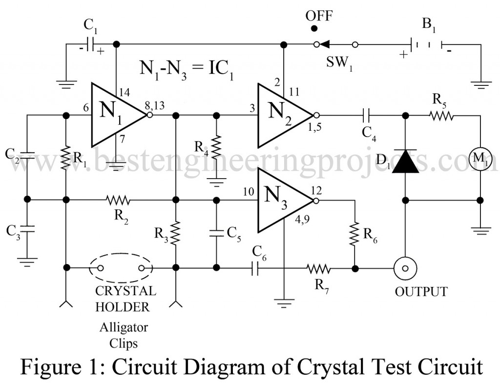
Crystal oscillators may fail to operate due to faulty design or faulty crystals. The circuit shown in figure 1 works well as a crystal tester for a wide variety of crystals and ceramic resonators over the 40-kHz to the 20-MHz range.
Circuit Description of Universal Crystal Test Circuit Using CA4007
The oscillator in figure 1 is a Pierce type that operates at the crystal’s parallel resonant frequency and presents about 30 pF capacitance to the crystal. The IC1 (CA4007 A) contains three pairs of complementary MOSFETs with the first (input at pin 6) functioning as a Pierce oscillator. The second (input at pin 3) drives a micro-ampere meter movement. The resistor R5 is selected to provide about 90% deflection with an active (good) crystal. The “tuning” meter from a discard stereo is usually ideal for this application. The other complementary pair (input at pin 10) provides a low-impedance output that can drive a frequency counter or provide a connection for an oscilloscope.
The crystal being tested can be inserted in the crystal holder or connected with an alligator clip. The input MOSFETs are well protected from electrostatic and leakage damage.
Check out other various testing circuits posted in bestengineeringprojects.com
- Speaker Polarity Test Circuit
- Servo Motor Tester Circuit Using 555 IC
- Zener Diode Tester Circuit
- Relay Tester Circuit
- 5 State Digital IC and Circuit Tester
PARTS LIST OF UNIVERSAL CRYSTAL TEST CIRCUIT
| Resistor (all ¼-watt, ± 5% Carbon) |
| R1 = 220 KΩ
R2 = 22 MΩ R3 = 15 KΩ R4 = 100 KΩ R5 = refer to text R6 = 10 KΩ R7 = 220Ω |
| Capacitors |
| C1 = 0.1 µF, 25V (Electrolytic Capacitor)
C2 = 100 pF (Ceramic Disc) C3, C5, C6 = 47 pF (Ceramic Disc) C4 = 30 pF (Ceramic Disc) |
| Semiconductors |
| IC1 = CA 4007A (Complementary Pair Plus Inverter IC)
D1 = 1N4001 (Rectifier Diode) |
| Miscellaneous |
| M1 = 200 – 500 µA meter
Crystal holder B1 = 9V Battery Output jack SW1 = ON/OFF switch |
