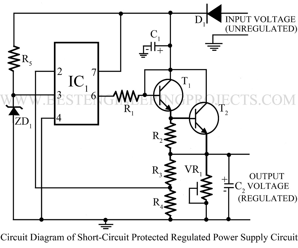
Various Power Supply-based projects are already available on bestengineeringprojects.com like short-proof variable power supply, stabilized power supply with short circuit indicator, Universal digital power supply, variable switching power supply, etc. Now here is a straightforward circuit of short circuit-protected regulated power supply utilizing very few components.
Circuit Description of Short Circuit Protected Power Supply
The electronics project short circuit protected variable power supply utilizing an op-amp 741, two NPN transistors, and a few passive components. Unregulated or fluctuating voltage is first regulated and smoothened by diode D1 and Zener diode ZD1. Resistor R5 is used as a current-limiting resistor. The output-regulated voltage is given to the non-inverting pin (pin 3) of IC1.
The output of IC1 from pin 6 is given to the base of the series regulator transistor T1 through resistor R2. Inverting pin of IC2 is connected to the voltage divider circuit at the output. In the beginning difference between its inverting pin (pin 2) & non-inverting pin (pin 3) make the transistor T1 ON. According to the input voltage of the IC, its output voltage also changed which is given to the base of the transistor and as a result output voltage is controlled.
Transistor T2 is used here for short-circuit protection. If the output current is increased or when a short circuit occurs, the voltage across resistor R3 is also increased which makes transistor T2 ON. When transistor T2 is on it gives a reverse bias to transistor T1 and as a result, no output voltage is available. In this way, the circuit short circuit-protected regulated power supply provides a regulated power supply with short circuit protection facility.
Check out other power supply circuits posted on bestengineeringprojects.com
- Adjustable Ripple-Regulated Power Supply Using 741
- Variable Switching Power Supply
- Universal Digital Power Supply Circuit
- Stabilized Power Supply With Short-Circuit Indication
- Short Proof Variable Power Supply
- Adjustable Bipolar Voltage Regulator Circuit Using LM337
PARTS LIST OF SHORT CIRCUIT-PROTECTED REGULATED POWER SUPPLY
|
Resistor (all ¼-watt, ± 5% Carbon) |
|
R1 = 200 Ω R2 = 47 Ω/1W R3, R4 = 10 KΩ R5 = 4.7 KΩ VR1 = 47 KΩ |
|
Capacitors |
|
C1 = 470 µF, 25V (Electrolytic capacitor) C2 = 100 µF, 25V (Electrolytic capacitor) |
|
Semiconductors |
|
IC1 = µA741 (Operational Amplifier) T1 = SL100 (Medium Power NPN Transistor) T2 = BC148 (General Purpose NPN Transistor) ZD1 = 1W D1 = 1N4007 (Rectifier Diode) |

Sir..I have a doubt.. I have given all connections but how to give supply connection?
The output secondary winding of transformer is connected through bridge rectifier to the input terminal at point as shown in circuit diagram [input voltage (unregulated )] section.
can u say at what voltage short circuit occurs