Various power supply-based project is already posted on bestengineeringprojects.com. Now, here is a stabilized power supply circuit with the facility of short-circuit indication. As we know that stabilized power supply is used for testing various electronics circuits and is very important for electronics geeks or hobbyists.
The circuit presented here is of a 5-stage stabilized power supply unit and it provides well-regulated output, which is essential for most electronics circuits for proper results. Another advantage of the circuit stabilized power supply with short-circuit indication has it provides an audio-visual indication if there is a short in the test circuit, and also cut-off the power supply immediately in order to save the valuable components. The four regulated outputs (12v, 9v, 6v, and 5v) and an unregulated output (18v) are obtained at their output and are selected by switch SW2 (rotary switch). The output taken is indicated by an analog voltmeter connected to the output rails as shown in the circuit diagram.
Circuit description of stabilized power supply with short-circuit indication
The circuit of stabilized power supply unit utilized voltage regulated IC for regulated output and a few other activities as well as passive components for audio-visual indication of short-circuiting. The input AC of 230V is stepped down using a 9V-0-9V stepped down transformer and is further rectified using a bridge rectifier built using diode D1 to D2. The rectified output is further filtered by 1000 µF of capacitor C1 and given to the regulator through switch SW1 as shown in the circuit diagram. The fixed regulated output of 12V, 9V, 6V, and 5V is obtained from IC1 through IC4 respectively. This power supply circuit is useful for loads requiring up to 200mA current.
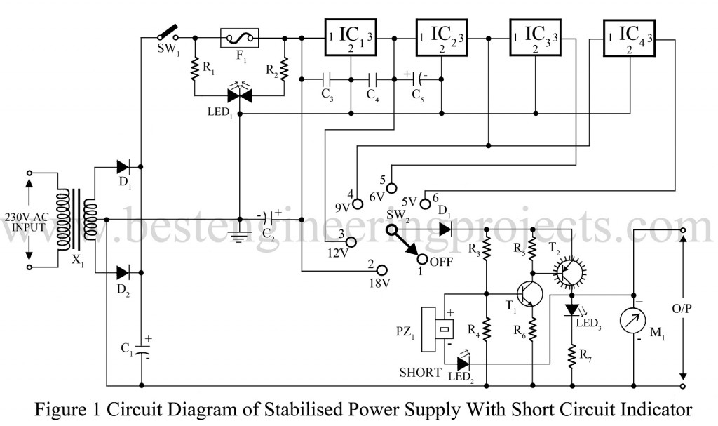
LED1 (bi-color LED) is used to indicate the fuse is intact or blown up. When power is available and the fuse is intact both the halves (red and green) are effectively in parallel to output a yellowish light. In the condition of fuse blown up, the green half goes off and only red light up to indicate. Transistors T1 and T 2 both conduct when the power to the circuit is switched on. The selected power supply is available at the collector of transistor T2 and is indicated by led3 and voltmeter. The negative terminal of piezo-buzzer PZ1 is connected to the output rail via LED2, so that piezo-buzzer remains silent as its negative terminal is also a full supply voltage. If there is a short circuit at the output, LED2 glows to activate the piezo-buzzer.
PARTS LIST OF STABILIZED POWER SUPPLY WITH SHORT-CIRCUIT INDICATION
|
Resistor (all ¼-watt, ± 5% Carbon) |
|
R1 = 820 Ω R2 = 1 KΩ R3 = 1.5 KΩ R4 = 10 KΩ R5 = 2.2 KΩ R6 = 100 Ω R7 = 1.2 KΩ |
|
Capacitors |
|
C1 = 1000 µF, 35V (Electrolytic Capacitor) C2, C5 = 100 µF, 35V (Electrolytic Capacitor) C3, C4 = 0.1 µF (Ceramic Disc) |
|
Semiconductors |
|
IC1 = 7812 (+12V Series Voltage Regulator) IC2 = 7809 (+9V Series Voltage Regulator) IC3 = 7806 (+6V Series Voltage Regulator) IC4 = 7805 (+5V Series Voltage Regulator) T1 = BC548 (General Purpose NPN Transistor) T2 = SK100 (Medium Power NPN Transistor) D1 – D3 = 1N4007 (Rectifier Didoe) |
|
Miscellaneous |
|
X1 = 230V AC Primary to 9V-0-9V 1A, secondary transformer SW1 = ON/OFF Switch SW2 = Rotary Switch F1 = 1A Fuse PZ1 = Piezo-buzzer LED1 = Bi-color LED LED2, LED3 Voltmeter |