Many instruments and equipment, such as function generators, transmitters, trans-receivers, high-quality stereo systems, and radio receivers, require ripple-free power supplies. The most significant feature required in a good quality power supply, besides load and line regulation, is minimum ripple as its output.
Circuit Description of Adjustable Ripple-Regulated Power Supply Using 741
In various applications where the ripple is not desired, the circuit adjustable ripple-regulated power supply using 741 shown in figure 1 for adjustable ripple regulated power supply works quite satisfactorily. Here the advantage of op-amps’ enormous gain is utilized along with op-amps’ property of keeping the inverting and non-inverting terminals at the same potential by the feedback loop comprising series-pass transistor T1, R4, VR2, and R3 op-amp 741 and diode D3. A minor difference in the two potentials at the input of the op-amp is highly amplified due to the IC’s enormous gain quality, which guides the series-pass transistor to bring the two input terminals of the op-amp to equal potentials at a very fast feedback repetition.
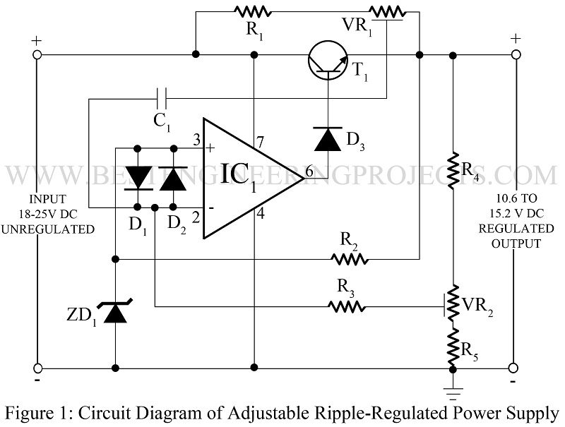
Resistors R1 and VR1 have been used in the circuit to provide the starting current to the circuit and also to sample the positive ripple of the input at the inverting input of the op-amp, thereby generating a negative ripple at the output. Once the circuit starts working, it is further stabilized due to constant current, resulting in a highly regulated power supply.
Here a 5.1V zener diode is used because this particular Zener provides the lowest temperature coefficient, i.e. it does not give any change in its voltage due to temperature change. Diode D1 and D2 have been incorporated into the circuit to protect the input of op-amp by latching both at the difference of 0.6V.
Since Vz, R4, VR2, and R5 are fixed, the output voltage is fully controlled by resistance, which varies between R5 (minimum) and R5 + VR2 (maximum). A sample of any change at the output due to load or input variation is reflected at the inverting input of the op-amp. This change is amplified by op-amp in the opposite phase and delivered to transistor T1 to compensate for the same.
Diode D3 opposes the flow of any reverse leakage current by transistor into the op-amp and thereby protects it. Ripple compensation is achieved as a portion of unregulated positive ripple id fed into the op-amp’s inverting input terminal which generates an amplified negative ripple at the output. Capacitor C1 is used to filter out DC voltage associated with the positive ripple done by varying R7. This negative ripple gets added to the positive ripple already in the output, ultimately nullifying it.
To adjust the circuit for the desired range, first of all, resistance VR1 is adjusted to give the required output voltage. The maximum permissible load is connected and then resistor R7 is set to ‘null’ the ripple. A sufficient series-pass element, having enough current gain, should be provided for a larger current. For high voltage requirements, the op-amp shall have to be floated along with the output level.
Check out other power supply circuits posted on bestengineeringprojects.com
- Variable Switching Power Supply
- Universal Digital Power Supply Circuit
- Stabilized Power Supply With Short-Circuit Indication
- Short Proof Variable Power Supply
- Adjustable Bipolar Voltage Regulator Circuit Using LM337
- Self Switching-off Power Supply
- Dual Polarity 5v from 9v Battery
- 3.7V to 5V, 5.3V and 6V Converter Circuit
PARTS LIST OF ADJUSTABLE RIPPLE REGULATED POWER SUPPLY
|
Resistor (all ¼-watt, ± 5% Carbon) |
|
R1 = 68 KΩ R2 = 1.2 KΩ R3 = 120 KΩ R4 = 33 KΩ R5 = 22 KΩ VR1 = 100 KΩ VR2 = 10 KΩ |
| Capacitor |
| C1 = 0.1 µF (Ceramic Disc) |
|
Semiconductors |
|
IC1 = 741 (General Purpose Operational Amplifier) T1 = 2N3055 (silicon NPN power transistor) D1 – D3 = 1N4001 (Rectifier Diode) ZD1 = 5.1V zener diode |
Hi. I would like to get a regulated output of 5v dc . The input voltage is variable 50mv to 5 volt ac. The frequency is 0-500 per second. The output would go the PIC microcontroller
How D1,D2 is protecting two terminal?