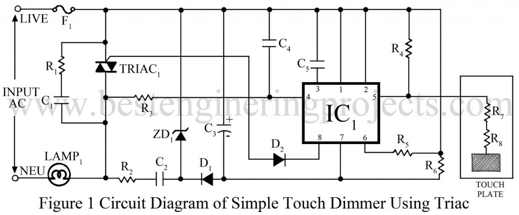
We have already posted a dimmer using a capacitor called “Light Dimmer Circuit.” Now, here is a Touch dimmer circuit using a triac.
Circuit Description of Touch Dimmer Circuit Using Triacs
The heart of the circuit touch dimmer using triac is the S576 (IC1), which provides an uncomplicated and elegant method of firing the triac.
The IC is not very sensitive to power glitches and works on the 15V dropped by R2 and C2. Zener Diode ZD1 clamps the voltage at 15V, while D1 and C3 smooth the supply. The RC snubber reduces interference. Resistors R7 and R8 are necessary and provide the touch plate. The triac firing signal is fed through D2, while R3 and C4 synchronize the circuit to the mains frequency.
When the touch plate is touched briefly from 50- 400ms, the lamp or load toggles between on and off. When the plate is touched for more extended periods, the load (i.e., the lamp) cycles between maximum and minimum power in 6.5 secs. The 50ms lower limit is set to avoid false triggering by picking up interference. The circuit can handle any amount of non-conductive power if the amperage of the triac is changed.
Check out other touch-operated switches posted on bestengineeringprojects.com
- Touch Switch Circuit using Transistor
- Touch Switch-Cum-Heat Operated Switch
- Clap Switch Cum Touch Switch
- Thermal Touch Switch using op-amp 741
- Simple Touch Switch Using Two Transistors
PARTS LIST OF TOUCH DIMMER USING TRAIC
|
Resistor (all ¼-watt, ± 5% Carbon) |
|
R1 = 10Ω R2 = 1 KΩ/1W R3 = 1.5MΩ R4, R7, R8 = 4.7 MΩ R5 = 470 KΩ R6 = 120 KΩ |
|
Capacitors |
|
C1 = 10 nF (Ceramic Disc) C2 = 220 nF (Ceramic Disc) C3 = 100 µF, 25V (Electrolytic Capacitor) C4 = 470 pF (Ceramic Disc) C5 = 47 nF (Ceramic Disc) |
|
Semiconductors |
|
IC1 = S576 (Dimmer IC) ZD1 = 15V D1, D2 = 1N4006 (Rectifier Diode) TRIAC1 = As per the power needed |
|
Miscellaneous |
|
F1 = 2Amp fuse Touch Plate |

Thank you for so much
Very helpful