The circuit for the clap switch is not a new idea for electronics hobbyists. After a long experiment here we design and verified a simple clap switch circuit.
Description of Clap Switch Circuit
The circuit presented here “Clap Switch” consists of a silicon transistor and is divided into three main sections i.e,
- Audio trigger stage
- Bistable multivibrator stage
- Relay operation stage
The audio trigger stage is built around a microphone and transistor T1. Microphone changes the sound of a clap in electrical signal and is given to the base of transistor T1 for required amplification. The positive output pulse from transistor T1 is given to the transistor-based multivibrator built around T2 and T3. With the first positive pulse transistor T1 starts conducting and transistor T3 remains off. Similarly, with the second positive pulse transistor, T3 starts conducting and T2 turns off.
Due to parameter mismatch of bistable multivibrator st the very instant transistor T2 conducts more than T3. When the MIC gets the clap sound or the sound of the whistle, a negative-going pulse appears at the common input of the bistable. It retards T2 as a result T3 is put in conduction and T2 in the off-stage.
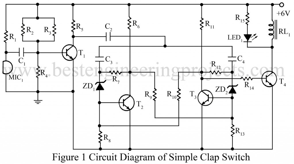
The relay operation stage is built around transistor T4 which is used as a relay driver. A LED is used in parallel with the relay for visual indication. For better performance, a battery is recommended for the power supply. AC adapter should not be used
Check out other clap switch and sound operated circuits posted in bestengineeringprojects.com
- Clap Switch Cum Touch Switch
- Clap Switch Circuit Using 555
- Sound Operated On-Off Switch
- Sound Operated Intruder Alarm with Flash
- Op-Amp 741 Based Sound Operated Light
PARTS LIST OF CLAP SWITCH CIRCUIT
|
Resistor (all ¼-watt, ± 5% Carbon) |
|
R1, R9, R10 = 10 KΩ R2, R3 = 1.5 MΩ R4 = 150 KΩ R5 = 2.2 KΩ R6, R11 = 1.2 KΩ R7 R12 = 2.5 MΩ R8, R13 = 22 KΩ R14 = 4.7 KΩ R15 = 1 KΩ |
|
Capacitors |
|
C1 – C4 = 0.1 µF (Ceramic Disc) |
|
Semiconductors |
|
T1 – T3 = BC148 (General Purpose NPN Transistor) T4 = BEL187 (General Purpose NPN Transistor) ZD1, ZD2 = 5.1V, 250mW LED1 |
|
Miscellaneous |
|
MIC1 = 34 LOD cond. Microphone RL1 = 6V, 100Ω Relay |