There are some projects from which every electronics hobbyist starts their journey toward electronics. Same like another hobbyist I had also started my journey of electronics projects by making a very basic project called a light-operated switch using a single transistor. After six long years of the journey today, I had again come up with a basic project which will surely help beginners. The project posted here is of Light Sensor Switch Circuit using LDR and 741 IC.
The project switches on the electrical bulb according to the intensity of light falling on the LDR.
You may also like:
- Automatic Light Operated Switch
- Automatic Fence Lighting with Alarm
- IC 555 Based Automatic Evening Lamp
- Automatic Night Lamp Circuit
- Dark Sensor using Arduino
Circuit Description of Light Sensor Switch Circuit using LDR and 741 IC
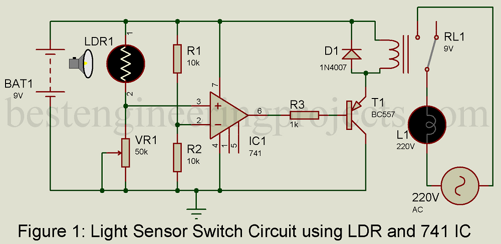
The circuit of Light Sensor Switch Circuit is shown in figure 1 and is built around a very popular operational amplifier IC, light-dependent resistor (LDR), a general-purpose PNP transistor, and a few other components like resistor, relay, etc.
For description, we had divided the entire circuit into three main sections
- Sensor unit
- Voltage comparator unit
- Switching circuit unit
Sensor unit:
The sensor is designed around an LDR and a variable resistor. We had used here GL5528 LDR photoresistor, but you can use any module as per the availability.
LDR is made from cadmium sulfide containing no or very few free electrons when not illuminated then its resistance is quite high. When it absorbed light, the electron is liberated and the conductivity of the material increases thus its resistance becomes low. The resistance rises to several Mega-ohm under dark.
LDR with variable resistance VR1 forms a voltage divider network. The output of this network is given to non-inverting input as shown in figure 1. The LDR is a variable resistor whose resistance change according to the intensity of light falling on it. Variable resistor VR1 is used to adjust the sensitivity of LDR i.e. on what intensity of light, the circuit triggers the load (Bulb).
Voltage comparator unit:
There is the various application of OP-amp out of which IC 741 is configured in voltage comparator mode which compares input voltage levels given to two input pins (Inverting and non-inverting pins) and produces the output. Resistor R1 and R2 form a voltage divider network that divides Vcc into two parts thus ½ Vcc volt is available at inverting input.
Another input voltage is taken from the voltage divider network using LDR and a variable resistor (VR1). Op-amp 741 compares these two voltage and produce output. If the voltage at pin 3 is high, the output of IC1 is also high, and if volts at pin 3 the low output of IC1 is low.
Switching Circuit:
The switching circuit is designed using a general-purpose PNP transistor BC557. When the output of IC1 is high, the transistor drives to the off state. As a result, Relay becomes dc-energized. When the output of IC741 is low, the transistor starts to conduct, and the relay becomes energized.
Working of the Circuit:
The LDR is a variable resistor whose resistance decreases with the increases in light intensity. When light falling on an LDR has low intensity (dependent upon adjustment of variable resistor VR1), its resistor is large enough and the voltage across VR1 is less than ½ Vref thus output if IC1 becomes low. This low output triggers the transistor T1 and drives the Relay, as a result, the bulb start to glow.
However, when light falling on LDR is of large intensity, the resistance of LDR falls and the voltage drop across VR1 is large enough (more than ½ Vcc). Thus, the output of IC1 becomes high. This high output drives the transistor into off state and as a result, the relay becomes de-energized.
PCB Diagram of Light Sensor Switch Circuit using LDR and 741 IC
The PCB diagram is designed using Proteus 8.1. The solder side and component side PCB is shown in figure 2 and 3 respectively. The figure shown here is scaled by 200%. You can directly download the actual size PCB diagram from the link given below.
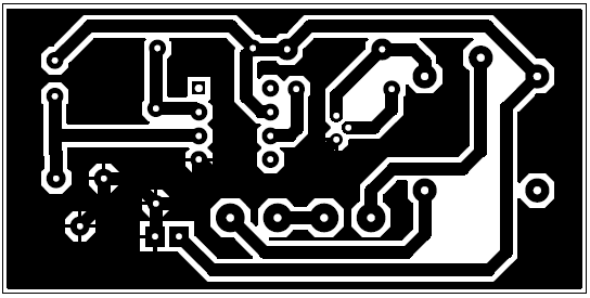
Figure 2: Solder Side PCB
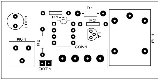
Figure 3: Component Side PCB

Figure 4: PCB Prototype
Click Here to Download the Actual size PCB Diagram in PDF format
PARTS LIST OF Light Sensor Switch Circuit using LDR and 741 IC
| Resistors (all ¼-watt, ± 5% Carbon) |
| R1, R2 = 10 KΩ
R3 = 1 KΩ VR1 = 50 KΩ |
| Semiconductors |
| IC1 = LM741
T1 = BC557 D1 = 1N4007 |
| Miscellaneous |
| LDR1 =
RL1 = 9V Relay |