While flowing up the discussion on bestengineeringprojects.com, one of our readers ask about a dynamic microphone pre-amplifier. The dynamic microphone pre-amplifier circuit is a bit different than other microphone pre-amplifier circuits because it consists two-stage amplifier section. Thus, before going through the circuit description we would like to make clear the dynamic microphones.
What is Dynamic Microphone?
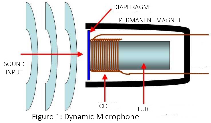
A dynamic microphone is a transducer that converts the sound signal into an electrical signal and works on the electromagnetic induction principle because it contains a moving coil. This microphone is also called a moving coil microphone. It consists of the conductor in the form of a coil placed between two strong permanent magnet poles. The duralumin metal diphagram is attached to the moving coil made from an aluminum ribbon. Dynamic microphone construction is shown in figure 1.
Description of Dynamic Microphone Pre-amplifier Circuit
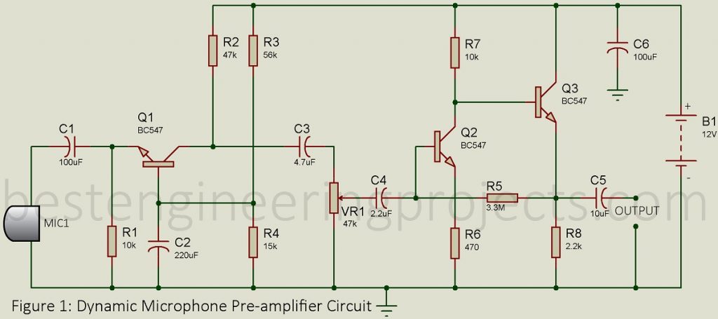
The circuit of the dynamic microphone amplifier is shown in figure 2. The circuit is basically a two-stage discrete amplifier. This circuit has inbuilt gain control. We had divided the entire circuit into two different sections for a better description.
Input Stage of Dynamic Microphone Preamplifier Circuit
For the input stage, the consideration is not the maximum voltage gain but the impedance matching of the source with the input impedance of the input stage. Some driving sources may require an input circuit to be an almost open circuit while others need an almost short circuit. Hence, we may be required to use CC (Common Collector) or CB (Common Base) configuration for the input stage for proper impedance match at the voltage or current gain. In certain other cases, the choice of configuration for the input stage is the minimization of noise and maximization of signal/noise power ratio. Thus, we had chosen a common base transistor amplifier.
Direct Coupled Amplifier for Dynamic Microphone Pre-Amplifier Circuit
Transistor T2 and T3 is a direct-coupled amplifier which is also referred to as a multistage amplifier. The choice of transistor configuration to be used for the intermediate stage in a multistage amplifier depends on the maximum voltage gain provided by the configuration. Hence, CC configuration can not be used since a stage of CC amplifier gives voltage gain less than unity. A single-stage CB amplifier, no doubt, gives voltage gain more than unity but the intermediate stage can not use even CB configuration since the overall voltage gain of the multistage amplifier using CB configuration is low, almost equal to the voltage gain of the last stage alone. This becomes evident from the following discussion.
The voltage gain AVk of any stage, say Kth stage is given by,
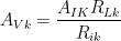
But RLk = Rck || Ri(k+1)
Hence RLk < Ri(k+1)
Assuming the stage to be identical i.e. assuming that Ri(k+1) = Rik, we conclude that RLk < Rik. Further, the maximum value of current gain AIK in CB configuration is hfe which is slightly less than unity. Hence as per the above equation, AVk for any CB stage except the last stage is less than unity. Hence, we conclude that even CB configuration is not suitable for use in the intermediate stage.
CE stage is popularly used for the intermediate stage since hfe for a CE stage is much greater than unity.
The overall gain of this circuit is +39dB which is approx. 90 time of input signal. The gain of the circuit can be controlled using variable resistor VR1. This circuit can be suitable for 30Hz to 100kHz signals.
PCB Diagram:
PCB diagram of Dynamic Microphone Pre-amplifier Circuit is designed using Proteus 8.1. Solder side and component side PCB are shown below.
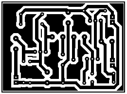
Figure 2: Solder Side PCB
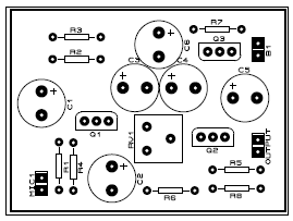
Figure 3: Component Side
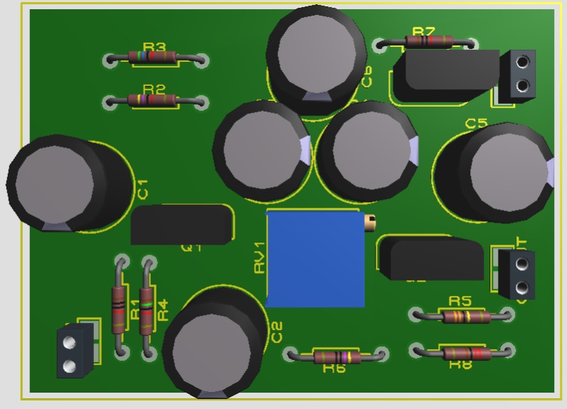
Figure 4: Author prototype of PCB
Click Here to Download PCB Diagram in PDF
Note: The circuit posted here is suitable for 200-ohm to 600-ohm dynamic microphones.
| Resistors (all ¼-watt, ± 5% Carbon) |
| R1, R7 = 10 kΩ
R2 = 47 kΩ R3 = 56 kΩ R4 = 15 kΩ R5 = 3.3 MΩ R6 = 470 Ω R8 = 2.2 kΩ VR1 = 47 kΩ (POT.) |
| Capacitors |
| C1, C6 = 100 µF
C2 = 220 µF C3 = 4.7 µF C4 = 2.2 µF C5 = 10 µF |
| Semiconductors |
| Q1, Q2, Q3 = BC547 |
| Miscellaneous |
| MIC1 = Moving Coil Microphone
BAT1 = 12V Battery or DC power Supply |
Thankyou for this sir! I really appreciate it. I’ll try this as soon as possible. More powers to you! Thanks again.