Signal transmission can be quite troublesome sometimes. To ensure that the signal is passed through a defined distance, here we have presented an “Audio Signal Tracer Schematic”. As mentioned in the title; ‘Audio Signal Tracer Schematic’, this project is implemented to troubleshoot audio signals transmission in electronic circuits and radio, etc.
It comprises two loudspeakers being Audio Signal Tracer and is packaged into a small hand-held test probe. The only power source required by the circuit is a battery and thus is more useful. Amplitude-modulated signals can also be detected by incorporating a diode detector in the circuit.
Working of the Audio Signal Tracer Schematic
Talking about the process of how this device works. Initially, we feed an audio signal which is also called a test signal into the tracer circuit at points CON1/CON2 from multiple points of a circuit to be tested. The point up to which the signal is clearly heard without any distortion is working fine. In cases, when the signal fades away, that part of the circuit is considered to have a fault.
With the use of a diode detector, we can also use it to trace other modulated signals such as FM radio signals.
Circuit Description of Audio Signal Tracer Schematic
The complete circuit of the project; ’Audio Signal Tracer Schematic’ is given in fig. 1. The circuit uses two ICs; LM358 (IC1) and TDA2822M (IC2) as its chief component. IC1 consists of two operational amplifiers which get operated from a single power source with a wide voltage range from 3V to 32V. These amplifiers are independent, internal frequency compensated, and high gain devices.
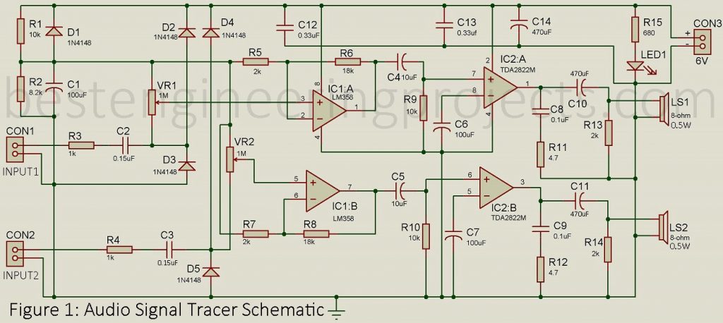
On the other hand, IC2 is a stereo amplifier with low power consumption. The output obtained from this IC can be directly fed to the speaker using decoupling capacitors as shown in the figure. Each signal from the microscope can be detected by the tracer circuit. It has high sensitivity.
The reason behind its sensitivity is a high input resistance of 1-mega-ohm (VR1 and VR2) included in the circuit that enables it to detect audible signals from multiple tone-control circuits and filters around the device. The signals fed to IC1 are amplified by the amplifiers present in the IC1.
Protection of Audio Signal Tracer Schematic
However, amplifiers contained in IC1 are totally independent of each other. The input to the first amplifier is protected by the combination of a resistor and two diodes; R3, D2, and D3 respectively. In the same way, R4, D4, and D5 are used to prevent damage to other amplifiers. The bias voltage required by the operational amplifier is provided by the combination of two resistors; R1, R2, diode D1, and a capacitor C1.
For volume adjustment of channels, potentiometers VR1 and VR2 are included. The voltage gains of two non-inverting operational amplifiers in IC1 are set to value ten. We can set the voltage gain to any values desired in the circuit. But, to protect a circuit from severe electromagnetic field effects and loudspeakers noise, the gain must not exceed 30.
In the case of IC2, each amplifier has an internal gain fixed at 100. This IC serves as a dual-channel output amplifier. The amplifier in IC2 is capable of driving 8 ohm or higher resistive loudspeakers and headphones.
As mentioned earlier, the circuit functions well with a 6V power supply from a battery. A supply greater than 6V can also be used. This signal tracing circuit can also be implemented as a dual-audio amplifier as well as a low-power stereo amplifier. For a 4-ohm speaker with a 9V power supply, this circuit offers an output power of 1W.
PARTS LIST OF AUDIO SIGNAL TRACER SCHEMATIC
| Resistors (all ¼-watt, ± 5% Carbon) |
| R1, R9, R10 = 10 KΩ
R2 = 5.2 KΩ R3, R4 = 1 KΩ R5, R7, R13, R14 = 2 KΩ R6, R8 = 18 KΩ R11, R12 = 4.7 Ω R15 = 680 Ω VR1, VR2 = 1 MΩ Potmeter |
| Capacitors |
| C1, C6, C7 = 100 µF, 16V (Electrolytic Capacitor)
C2, C3 = 0.15 µF (Ceramic Disk) C4, C5 = 10 µF, 16V (Electrolytic Capacitor) C8, C9 = 0.1 µF (Ceramic Disk) C10, C11, C14 = 470 µF, 16V (Electrolytic Capacitor) C12, C13 = 0.33 µF (Ceramic Disk) |
| Semiconductors |
| IC1 = LM358 (Dual op-amp)
IC2 = TDA2822M (Stereo op-amp) D1 – D5 = 1N4148 (Small signal diode) LED1 = 5mm LED |
| Miscellaneous |
| CON1 – CON3 = 2-PIN Connector
LS1, LS2 = 8-ohm, 0.5W Speakers 6-volt battery |