The “Simple Warning Alarm” circuit is creatively designed, leveraging the abilities of a transistor to produce clear and easily audible alerts, like notifications or distinct sounds. Its flexibility allows it to effortlessly integrate with a wide arrangement of security devices, such as burglar alarms and fire alarms, offering a dependable auditory indication of the device’s operational status. This straightforward yet efficient solution not only enhances the overall effectiveness of security setups but also ensures that critical circumstances are promptly detected, making it an invaluable addition to any security-conscious environment.
Description of Simple Warning Alarm Circuit
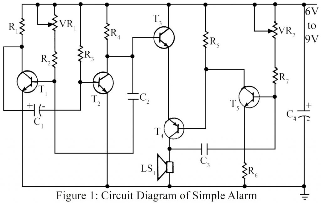
The “Simple Warning Alarm” circuit, demonstrated in Figure 1, employs a configuration of four NPN transistors along with a single PNP transistor. Specifically, NPN Transistors T1 and T2 collaborate to form a low-frequency astable multivibrator. By manipulating the setting of the variable resistor VR1, the frequency of this multivibrator can be finely adjusted within a range spanning from 1 Hz to 10 Hz.
This adjustable frequency parameter directly affects the pulse of the audible beeping produced by the circuit. To illustrate, if the frequency of the multivibrator is set at the lower limit of 1 Hz, the resulting beeping speed corresponds to this frequency. Conversely, as the frequency setting increases, the beeping speed proportionally accelerates, providing a direct correlation between the multivibrator’s oscillation rate and the audibility of the alarm.
PNP transistor T4 and NPN transistor T5 form a complementary pair Audio Frequency oscillator. Collector supply to transistor T4 is given through T3. Transistor T3 is used here as a switching transistor and is used to switch the audio frequency oscillator according to the frequency of the multivibrator.
The tone of the sound can be varied by variable resistor VR2. The warning alarm circuit can be easily assembled on general-purpose Veroboard. An ordinary 6V to 12V battery or regulated power supply can be used.
PART LIST OF SIMPLE WARNING ALARM
|
Resistors (all ¼-watt, ± 5% Carbon) |
|
R1, R4 = 10 KΩ R2 = 180 KΩ R3 = 470 KΩ R5 = 3.3 KΩ R6 = 56 Ω R7 = 100 KΩ |
|
Capacitors |
|
C1 = 1 µF (Electrolytic Capacitor) C2 = 0.02 µF (Ceramic Disc) C3 = 0.01 µF (Ceramic Disc) C4 = 100 µF/16V (Electrolytic Capacitor) |
|
Semiconductors |
|
T1, T2, T3 = BC548 (general-purpose NPN bipolar junction transistor) T5 = SL100 (general purpose, medium power NPN transistor) T4 = SK100 (general purpose, medium power PNP transistor) |
|
Miscellaneous |
|
LS1 = 8Ω, 1W Loud Speaker |
You may also like:
- Multi Sound Generator Circuit
- Electronic Siren Circuit
- Machine Sound Generator Circuit
- Tune Player using Arduino
- Siren Circuit
what are the values in ohms for VR1 and VR2?