TH02 is a consumer-grade digital temperature and humidity sensor. Although it can operate with a humidity range of 0-100% RH, it provides reliable or highly accurate data when the environmental conditions are between 0-70°C and 0-80% RH. The reason to use the TH02 sensor is that it provides a reliable reading in most home and daily applications if operated at its measuring range. It comes with its output calibrated in standard I2C format. In this article “Interfacing Temperature and Humidity Sensor TH02 with Arduino”, you will learn how to interface TH02 temperature and humidity sensors with Arduino.
Features of Temperature and Humidity Sensor TH02
- Temperature measurement range 0 ~ 70°C
- Humidity measurement range 0 ~ 80% RH
- Low Power Consumption:350 µA during RH conversion
- Digital output, I2C interface
- Excellent long-term stability
Specification of Temperature and Humidity Sensor TH02
- Operating Voltage: DC:2.0-5.5V
- Operating Range (humidity): 0 ~ 100% RH
- Measuring Range (humidity) 0 ~ 80% RH
- Temperature Range: 0 ~ 70 ℃
- Humidity Accuracy: ± 4.5% RH
- Temperature Accuracy ± 0.5 ℃
Components Required for Arduino TH02 Interface
- Arduino UNO/NANO × 1
- TH02 Sensor × 1
- 16×2 I2C LCD × 1
- Connectors
The working of the circuit and its interface with Arduino is similar to the ATH20 sensor. More about the ATH20 sensor on this link.
Working of the circuit
The working of the circuit is very simple. TH02 sensor reads environmental temperature and humidity and converts it into digital format. The Arduino request the temperature and humidity, TH02 send the value through an I2C connection. The value provided from TH02 is then displayed over a 16×2 alphanumeric I2C display. Here in this article, we are using Seeeduino nano instead of Arduino nano. Both boards share the same pin configuration and controller but Seeeduino nano has an I2C grove.
Circuit Description of Arduino AHT02 Interface
Arduino analog pins A4 and A5 are also used for SDA(Serial Data) and SCL(Serial Clock) connection respectively. Thus pin SDA and pin SCL of TH02 and 16×2 I2C LCD are connected to Arduino A4 pin and A5 pin respectively. The 5V supply is connected to the Arduino and it is also connected to VCC of TH02 and VDD of LCD. Similarly, the GND pin from Arduino is connected to the GND pin of TH02 and VSS of LCD. The interfacing of Arduino and TH02 is shown in the circuit diagram.
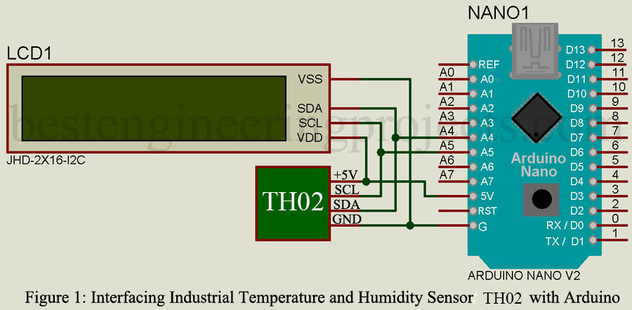
If we want to connect multiple I2C devices we can use an I2C connection hub. Also, the use of an I2C connection hub avoids the entanglement of wires. Each I2C device has a unique address to avoid conflict during data communication between multiple devices. The TH02 sensor has a serial I2C serial interface with a 7-bit address of 0x40 and the 16×2 I2C LCD consists of 8 different address that allows connection of 8 different 16×2 I2C LCDs at once. These addresses of LCD can be selected by a combination of 3 pins A0 A1 A2. Here, we are using a 16×2 I2C LCD because it allows data communication only with 2 pins (SDA and SCL).
Further details of how to interface a traditional 16×2 LCD are discussed in full detail on this video link.
Software code
The software code is written in C++ language (Arduino compatible) and is compiled using Arduino IDE. The software code required three different libraries.
- Wire. h (For I2C connection)
- Th02_dev.h (For TH02 Sensor)
- LiquidCrystal_I2C.h (For I2C Liquid Crystal)
|
1 2 3 4 5 6 7 8 9 10 11 12 13 14 15 16 17 18 19 20 21 22 23 24 25 26 27 28 29 30 31 32 33 34 35 36 37 38 39 40 41 42 43 44 45 46 |
//Interfacing TH02 temperature and humidity sensor with arduino #include <Wire.h> //I2C Wire library #include <TH02_dev.h> #include <LiquidCrystal_I2C.h> //I2C Library LiquidCrystal_I2C lcd(0x27,16,2); // Decrearation of address no. of row and column of I2C LCD void setup() { Serial.begin(9600); lcd.init(); // initialize the lcd lcd.backlight(); lcd.setCursor(0,0); lcd.print("TH02 Interface"); lcd.setCursor(2,1); lcd.print("with Arduino"); TH02.begin(); delay(2000); Serial.println("TH02_dev is available.\n"); } void loop() { lcd.clear(); float humi, tempe; tempe = TH02.ReadTemperature(); humi = TH02.ReadHumidity(); lcd.setCursor(0,0); lcd.print("Temp:"); lcd.setCursor(6,0); lcd.print(tempe); lcd.print((char)223); lcd.print("C"); lcd.setCursor(0,1); lcd.print("Humi:"); lcd.setCursor(6,1); lcd.print(humi); lcd.print("%"); Serial.print("humidity: "); Serial.print(humi*100); Serial.print("%\t temerature: "); Serial.println(tempe); delay(1000); } |
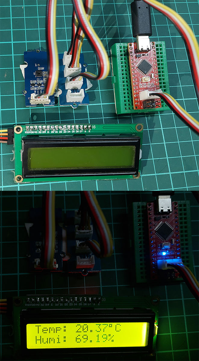 Figure 2: Author prototype