In this article, you will learn about TDS Sensor and Arduino Interfacing. TDS stands for Total Dissolved Solids and represents the amount of total dissolved solids (organic and inorganic substances) in water. TDS value is related to water quality. Typically, the higher the TDS value, the poorer the water quality. Pure water has a TDS value of 0, and the TDS value increases for increasing dissolved solids. But do remember that measuring the TDS value doesn’t provide you with the information on whether the dissolved solids are healthy for the human body or not. The below table provides the general idea of what the TDS value represents.
| Levels of TDS (mg/l) | TDS Rating |
| Less than 300 | Excellent |
| 300 – 600 | Good |
| 600 – 900 | Fair |
| 900 – 1200 | Poor |
| Above 1200 | Unacceptable |
TDS sensors are used to measure the TDS value of the water. TDS sensor consists of two components i.e Control Unit and TDS probe. The Control Unit is not waterproof and the TDS sensor probe is waterproof which is immersed in water.
Features
- Easy to Implement provides Analog output signal
- 3.3V/5V input voltage support
- Waterproof probe
- Arduino Compatibility
Specifications
- Input voltage: 3.3V / 5V
- Output Voltage: 0 ~ 2.3V
- Working Current current: 3 ~ 6mA
- TDS Measurement Range: 0 ~ 1000ppm
- Analog Interface
Components Required For TDS Sensor and Arduino Interfacing
- Arduino UNO/NANO × 1
- TDS sensor with its probe × 1
- 16×2 I2C LCD × 1
- Connectors
Working Principle of TDS Sensor
TDS sensors measure the electric charge discharge between the two needles of a sensor probe. When an excitation source is given to the sensor probe immersed in water electric charges are conducted by the ions of dissolved materials between the needles. These electric charges are measured by the controlling unit and the resulting TDS value in ppm (parts per million) is sent to the display.
Circuit Description of TDS Sensor and Arduino Interfacing
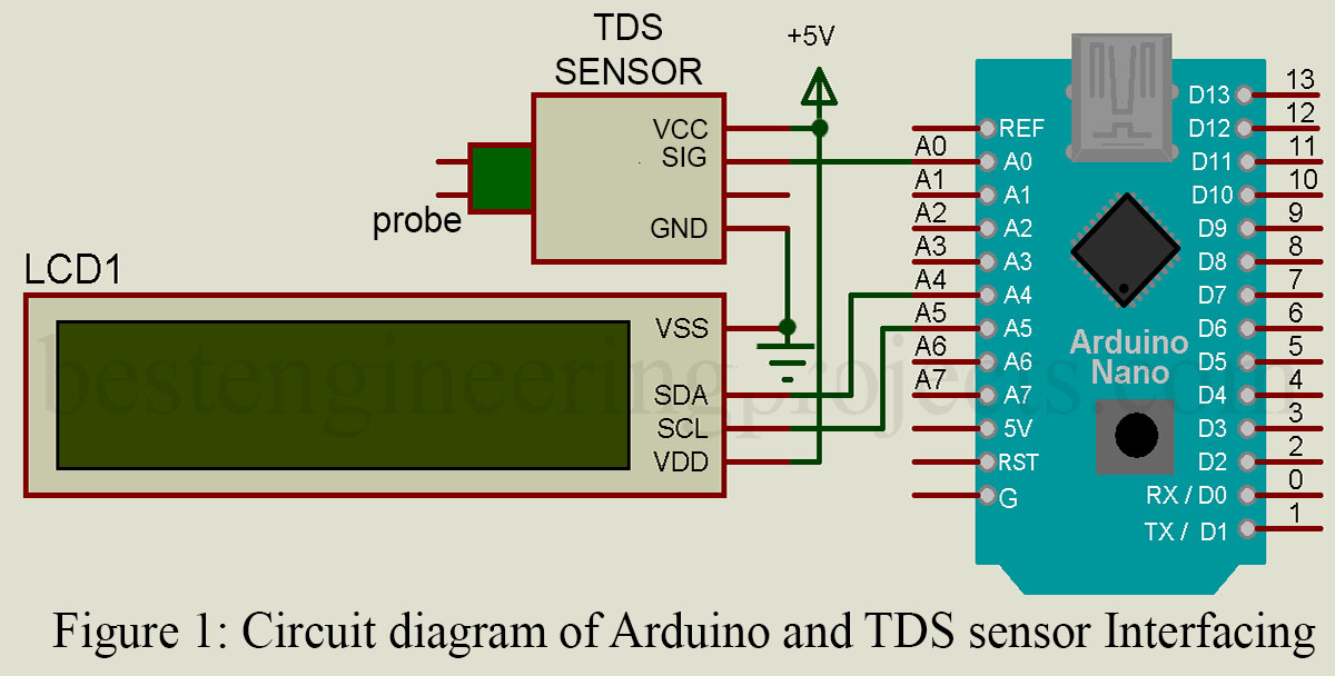
TDS sensor consists of 3-pin VCC, GND, and an analog signal pin. Connect the VCC of the TDS sensor to the 5V or 3.3V of the Arduino board. The analog signal pin of the sensor is connected to the A0 analog pin of the Arduino board and the GND pin of both devices is also connected.
For the connection of the 16×2 I2C LCD, connect SDA and SCL pins to the A4 (SDA) and A5(SCL) pins of the Arduino board. The 5V and GND pins of the Arduino board are connected to the VDD and VSS pins of the display respectively.
For the proper measurement of the TDS value, the probe should not be too close to the water container otherwise it will affect the reading. TDS sensors are incapable of measuring the TDS value of the flowing water and TDS probes cannot be used in water above 70℃. This rating of the TDS probe depends on the probe used, so make sure to properly note it down.
 Software Code: Software Code is written in Arduino programming language (C/C++) and is compiled using Arduino IDE. One library for I2C LCD is used. The software code measures the voltage from the TDS sensor, converts it into TDS value, and displayed it over LCD.
|
1 2 3 4 5 6 7 8 9 10 11 12 13 14 15 16 17 18 19 20 21 22 23 24 25 26 27 28 29 30 31 32 33 34 35 36 37 38 39 40 41 42 43 44 45 46 47 48 49 50 51 52 53 54 |
//Software code for arduino and TDS interfacing #include <LiquidCrystal_I2C.h> LiquidCrystal_I2C lcd(0x27,16,2); #define TdsSensorPin A0 int ADC_value; unsigned long int avgval_ADC; int buffer_tds[10],temp1; void setup() { Serial.begin(115200); pinMode(TdsSensorPin,INPUT); lcd.init(); lcd.backlight(); } void loop() { lcd.clear(); for(int i=0;i<10;i++) { buffer_tds[i]=analogRead(TdsSensorPin); delay(30); } for(int i=0;i<9;i++) { for(int j=i+1;j<10;j++) { if(buffer_tds[i]>buffer_tds[j]) { temp1=buffer_tds[i]; buffer_tds[i]=buffer_tds[j]; buffer_tds[j]=temp1; } } } avgval_ADC=0; for(int i=2;i<8;i++) avgval_ADC+=buffer_tds[i]; float voltage_value = (float)avgval_ADC*5.0/1024.0/6; float TDS = (133.42/voltage_value*voltage_value-255.86*voltage_value*voltage_value + 857.39*voltage_value)*0.5; lcd.setCursor(0,0); lcd.print("TDS Value ="); lcd.setCursor(0,1); lcd.print(TDS); lcd.setCursor(10,1); lcd.print("PPM"); delay(1000); } |