In this article, you will learn about the effect of temperature on the TDS of water and finally, you will learn how to make a “Temperature Compensated Arduino TDS Meter”.
TDS (Total Dissolved Solids) is the sum of organic and inorganic substances dissolved in water and, the methods used for the measurement of TDS value are Gravimetric Analysis and the Measurement of Electric Conductivity (EC). The gravimetric analysis provides reliable TDS value but it is time-consuming and is not very applicable when analyzing a lot of samples. So the measurement of TDS through Electric Conductivity is extensively used. Previously we had posted about the TDS sensor and its interfacing with Arduino in this article.
The electric conductivity of the liquid is the ability to conduct an electric charge. It depends on the concentration of ions and the temperature of measurements. The relationship between the EC and TDS can be represented by
TDS (mg/L) = k x EC (μS cm)
The value of correlation factor k will increase along with the increase of ions in water and varies between 0.55 and 0.8. The above relation may show that the relationship between TDS and EC is directly linear but that’s not true. It depends on the activity of specific dissolved ions, the average activity of all ions in the liquid, and ionic strength.
As TDS is directly related to conductivity, conductivity increases as the temperature increases, eventually affecting TDS. For every 1℃ rise in temperature, conductivity rises by 2–4%. If water temperature increases, the mobility of an ion increases, increasing conductivity. Also, the solubility of the many salts and minerals increases as the temperature increases, affecting the ion concentration in water, and as a result, conductivity increases.
If the temperature of the water increases, the evaporation rate of water increases, which in turn increases the concentration of the dissolved ion resulting in higher conductivity, eventually leading to a higher TDS value.
How TDS Sensor Works
TDS sensor uses conductivity to measure TDS value and since the temperature has a direct effect on conductivity, almost every TDS sensor is calibrated at a specific temperature i.e at 25℃. So, temperature compensation needs to be done to get accurate readings at specific temperatures. Some TDS sensors come with temperature compensation which allows you to directly read the TDS value at any temperature. If your TDS sensor does not contain any temperature compensation, you need to introduce it and calculate the correct TDS value at that temperature. For this, you need a waterproof temperature sensor for the measurement of water temperature. The Electric Conductivity (EC) at that temperature can be calculated by using the formula given below.
EC at 25℃ = 1+0.020 (temperature measured−25℃)
Thus, calculating the Electric Conductivity (EC) at the temperature measured by the temperature sensor allows the calculation of the TDS value at that temperature.
To calculate TDS with temperature compensation, first, we have to calculate Compensation Factor.
Compensation_Factor = 1.0*0.02*(Measured_Temperature-25-0)
TDS_Voltage = Measured_Voltage/Compensation_Factor
TDS = (133.42/TDS_Voltage*TDS_Voltage-255.86*TDS_Voltage*TDS_Voltage + 857.39*TDS_Voltage)*0.5
Information on the “Interfacing of a TDS sensor with Arduino” can be obtained in this article.
Circuit Description of Temperature Compensated Arduino TDS Meter
For the temperature measurements, we have used a waterproof version of the DS18B20 temperature sensor and for the display, we used a 16×2 I2C LCD but we can also use an I2C OLED Display or any other that you are compatible with.
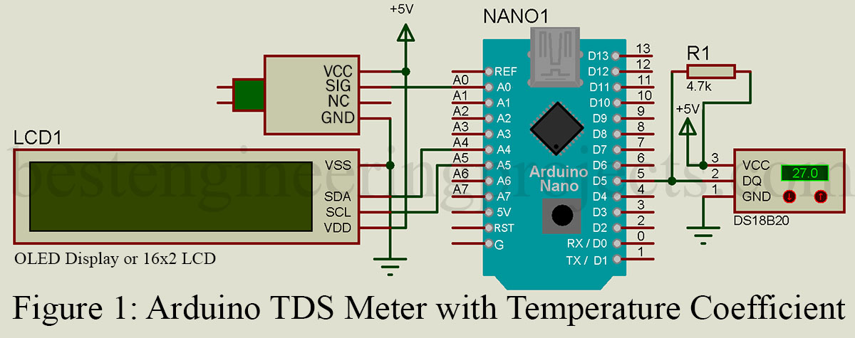
The circuit connection between the DS18B20 temperature sensor data pin (DQ) is connected to the Digital pin D5 of the Arduino NANO. Also, the analog signal pin SIG of the TDS sensor is connected to the analog pin A0 of the Arduino NANO. Similarly, for the 16×2 I2C LCD connection SDA and SCL pins are connected to the SDA and SCL (analog pin A4 and A5) respectively of Arduino NANO.
The temperature sensor DS18B20 used here is discussed in more detail in this article.
Software Code:
Software code is very simple and easily understandable. At first, it includes two libraries for LCD and DS18B20 temperature, and then a few variables are defined and declared. After that in the setup function, the initialization of the temperature sensor and LCD is done. In the Loop function, at first, we measure the temperature and voltage output of the TDS sensor. Here for accuracy, we measure voltage multiple times and took the average value. After that, we calculate the compensate_factor and then compensate voltage. Now, this compensating voltage is converted to a TDS value. At last Temperature value and TDS, value is displayed over LCD.
|
1 2 3 4 5 6 7 8 9 10 11 12 13 14 15 16 17 18 19 20 21 22 23 24 25 26 27 28 29 30 31 32 33 34 35 36 37 38 39 40 41 42 43 44 45 46 47 48 49 50 51 52 53 54 55 56 57 58 59 60 61 62 63 64 65 66 67 68 69 70 71 72 73 74 75 76 |
//Software code for temperature compensated arduino TDS meter #include <LiquidCrystal_I2C.h> #include <OneWire.h> #include <DallasTemperature.h> LiquidCrystal_I2C lcd(0x27,16,2); // Data wire is plugged into port 5 on the Arduino #define ONE_WIRE_BUS 5 // Setup a oneWire instance to communicate with any OneWire devices (not just Maxim/Dallas temperature ICs) OneWire oneWire(ONE_WIRE_BUS); // Pass our oneWire reference to Dallas Temperature. DallasTemperature sensors(&oneWire); #define TdsSensorPin A0 int ADC_value; unsigned long int avgval_ADC; int buffer_tds[10],temp1; void setup() { Serial.begin(115200); pinMode(TdsSensorPin,INPUT); sensors.begin(); lcd.init(); lcd.backlight(); } void loop() { lcd.clear(); sensors.requestTemperatures(); float Temperature = sensors.getTempCByIndex(0); float CompensationFactor = 1.0+0.02*(Temperature-25.0); for(int i=0;i<10;i++) { buffer_tds[i]=analogRead(TdsSensorPin); delay(30); } for(int i=0;i<9;i++) { for(int j=i+1;j<10;j++) { if(buffer_tds[i]>buffer_tds[j]) { temp1=buffer_tds[i]; buffer_tds[i]=buffer_tds[j]; buffer_tds[j]=temp1; } } } avgval_ADC=0; for(int i=2;i<8;i++) avgval_ADC+=buffer_tds[i]; float voltage_value = (((float)avgval_ADC*5.0/1024.0/6)/CompensationFactor); float TDS = (133.42/voltage_value*voltage_value-255.86*voltage_value*voltage_value + 857.39*voltage_value)*0.5; lcd.setCursor(0,0); lcd.print("TDS:"); lcd.setCursor(4,0); lcd.print(TDS); lcd.setCursor(10,1); lcd.print("PPM"); lcd.setCursor(0,1); lcd.print("Temp:"); lcd.setCursor(5,1); lcd.print(Temperature); lcd.setCursor(10,1); lcd.print((char)223); lcd.print("C"); delay(1000); } |
PCB Diagram: PCB of Temperature Compensated Arduino TDS Meter is designed using Altium Design. The actual side Solder side and component side PCB are shown in figure 3 and 4 respectively. Click on download for the printable PCB File.
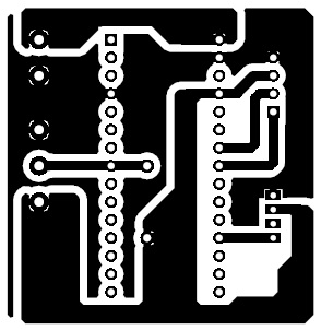 Figure 3: Solder Side PCB
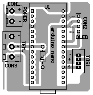 Figure 4: Component Side PCB
Great info, thanks! for sharing it.
maybe anyone can help, what is the meaning (133.42), (255.86), (857.39), (0.5) what value is?
TDS = (133.42/TDS_Voltage*TDS_Voltage-255.86*TDS_Voltage*TDS_Voltage + 857.39*TDS_Voltage)*0.5