Currently, in the market, a large number of GPS projects are distributed. You might be wondering what is different here? Well, the GPS receiver we are talking about is solely based on AVR- microcontroller. The project collects information from the satellite and so is more practical than other systems that demand wireless network connections as cellphones or Internet to operate.
This GPS receiver system is a boon to remote areas and can be used as a base to work in other research areas. It works with the satellite to track the exact location and calculate the standard time based on the latitudinal and longitudinal position of that place. Information received from the satellite and the standard coordinated universal time (UTC) are also considered during time calculation.
Circuit Description GPS Module Interface with ATmega16
The GPS is made up of three major elements; a GPS receiver module, Atmega16 microcontroller, and LCD. The receiver module intakes satellite data, the microcontroller processes that signal and LCDs the collected information including latitude, longitude, and time details of that place. There is a separate power section that powers the entire circuit.
Fig.1. reflects the complete circuit layout of the entire project. To establish the connection between the microcontroller and the GPS module, a 3-wire cable is required. The signal passed from the GPS module through Transmit pin (TXD) is received by the microcontroller (IC2) at the receive pin (RXD). Two resistors; R5 and R6 can be added to the circuit to pull those pins high. But, in this circuit, the microcontroller has inbuilt pull-up pins are port D and hence the resistors can be avoided.
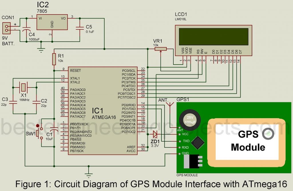
Power supply arrangement for GPS Module Interface with ATmega16
A dedicated power circuit is designed to supply the power required by the circuit. The circuit is made up of a 250mA secondary transformer, bridge rectifier module BR1, and capacitor C1. When a 230V AC mains is fed to the power circuit, a 9V, 250mA secondary transformer steps down the supply voltage and it is then rectified and filtered by rectifier module and capacitor C1 respectively. A 7805-voltage regulator is used to produce regulated voltage. Once the power supply flows through the circuit, LED1 glows. For the microcontroller and LCD, a regulated 5V DC is supplied. GPS module requires 3.3V and so a zener diode is used to convert the regulated 5V to 3.3V.
Using suitable converters, a 9V AC mains adaptor or 9V battery can also be used as the power source for the circuit. To connect the battery to the circuit, an additional switch S1 can be used.
LCD.
For this particular project, we used a 16×2 LCD module. Four data lines; D4-D7 are used for data transfer. After transferring 4-bit data two times, the data transfer process between the microcontroller and HD44780 is terminated.
Data lines D4-D7 of LCD are connected with PC4-PC7 pins in port C of the IC2. Similarly, other pins such as read/write (R/W), register-select (RS), and enable (E) of the LCD are connected to PD6, PC2, and PC3 of IC2, respectively.
GPS module.
The output data from the satellite serve as the input information to the GPS module. The latitudinal and longitudinal information of a place helps to identify the precise location and time of that place. Using this information, it is so easy to track the exact location of that place on the map.
You can take help from popular software like Google Maps to track down the location. It’s much easy to use the application as well, just type the latitude and longitude in a standard format and hit the search button and there you have it location details of that place.
Software Program for GPS Module Interface with ATmega16
The source code of the project is written in ‘C’ which is a common programming language and much easier to understand, in an AVR studio.
NMEA protocol.
This project is based on the idea of the NMEA (National Marine Electronics Association) protocol. The GPS module uses a portion of that protocol; NMEA-0183 that has a set of information written using ASCII characters in a standard format. GPS module passes this package of information continuously to the interfacing device. The message code is identified with the ‘$’ (hex 0x24) sign at the start and the (hex 0x0D 0x0A) sign at the end.
Information like GGA, GGL, GSA, GSV, RMC, VTG, and ZDA is included in this message. However, here we only use the GGA message that comprises time, position, and fixed data for this application. The standard format of GGA is given below:
$GPGGA, 002153.000, 3342.6618,
N,11751.3858, W, 1.2, 27.0, M, -34.2,
M,,0000*5E
Each entity separated by the comma (‘,’) is dedicated information and in this project, we make use of five fields that represent time, latitude, latitude-direction, longitude, and longitude-direction and these fields are 2nd, 3rd, 5th, 4th and 6th fields, in the standard GGA format.
The source code for the project is divided into two parts for simplicity; ‘gpsb.c’ which represents the core program and ‘lcd2.h,’ which is a driver file for the LCD module.
Click Here to Download Software Code
This program outputs coordinate values and entering these values in a world map, you can trace the location on your own. To see the exact standard time, look at the time details produced in this project.
PARTS LIST OF GPS MODULE INTERFACE WITH ATMEGA16
| Resistors (all ¼-watt, ± 5% Carbon) |
| R1 = 10 KΩ
VR1 = 10 KΩ Preset |
| Capacitors |
| C1 = 10 µF (Electrolytic Capacitor)
C2, C3 = 22Pf (Ceramic Disc) C4 = 1000 µF, 16V (Electrolytic Capacitor) C5 = 0.1 µF (Ceramic Disc) |
| Semiconductors |
| IC1 = ATmega16 (Microcontroller)
IC2 = 7805 (5V series voltage regulator) ZD1 = 3.3V Zener Diode |
| Miscellaneous |
| SW1 = Push-to-on Switch
X1 = 16MHz Crystal Oscillator CON1 = 2 pin connector for battery Antenna |
Other project-based on GPS posted in bestengineeringprojects.com
- DIY Distance Measurement using GPS and ATmega328P
- GPS Navigator Circuit using ATmega 16
- GPS and GSM based Vehicle Tracking System
- Accident Detection and Alert System using Arduino