The project ESP8266 Temperature Logger using PIC16F887 is built up using a PIC16F887 microcontroller (MCU), ESP8266 WiFi module, and a ThingSpeak API. Previously, we posted Arduino and ESP8266-based webservers and this project is somehow similar.
Introduction to ESP8266 Temperature Logger using PIC16F887
Here is a PIC16F887 microcontroller and ESP8266-based temperature logging system. The project; ‘ESP8266 Temperature Logger using PIC16F887 monitor’s the temperature of the vicinity simultaneously and provides details of the information collected. Well, the project also incorporates a modern concept; ThingSpeak which ensures safe storage and retrieval of data from things over the wide internet zone.
It is an IoT(Internet of things) application and API, it is an open-source platform and is gaining more popularity for this reason. This platform ensures the possibility to make use of data from different electronic devices, sensors, etc., by storing it on the internet and then making required observations to conclude the proper analysis of that information.
Other Data Logger projects posted in bestengineeringprojects.com
To obtain the temperature details from the project ESP8266 Temperature Logger using PIC16F887, you can log in to the browser on your device and use ThingSpeak API through Wifi.
Circuit Description of ESP8266 Temperature Logger using PIC16F887
Fig. 1 below gives details of the circuit layout of this project. The project includes microcontroller PIC16F887 MCU (IC4), ESP8266 Wi-Fi module, logic-level shifter, LM35 temperature sensor (IC3), 3.3V regulator LM1117-3.3 (IC2), 5V regulator 7805 (IC1), and 16×2 LCD module (LCD1) as the building blocks.
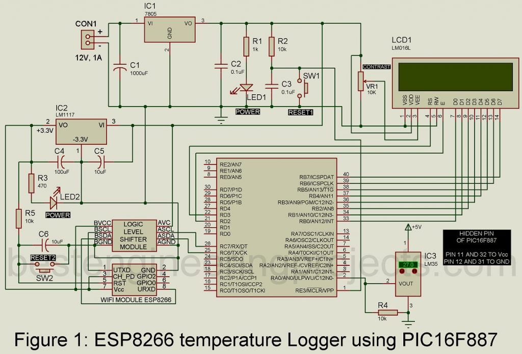
The entire circuit is powered using two power sources; 5V is required for PIC16F887, LCD, and Logic-Level Shifter IC whereas the ESP8266 module requires 3.3V. Since this ESP WiFi module intakes a regulated 3.3V altogether, you can replace IC2 with an adjustable voltage regulator, but be sure the voltage is precisely 3.3V.
The temperature sensor IC3 collects data and then forwards it as input to IC4 through pin 2. The IC4 is responsible to transmit data to the Wifi module(ESP8266) via a logic level shifter. Finally, we can read the recorded temperature details on the screen of our gadgets; smartphones, and laptops browsing through the ThingSpeak website once the WiFi module executes the data transmission process.
We establish the connection between the Wi-Fi modem of the user to ESP8266 Wi-Fi module and the temperature details are loaded onto the website of ThingSpeak, which allows us to view the statics of temperature data on our devices through the browser.
For visual interpretation of the project, LCD(pins D0-D7) is interfaced to IC4 (port B) which displays information about the circuit status and recorded data.
Software of ESP8266 Temperature Logger using PIC16F887
The programming is done in C language which makes it simpler to understand. We used MPLAB IDE version 8.9.1 and HI-TECH C compiler version 9.83.0.10920 to compile the source code. MPLAB ICD 2 programmer board was used to load the program onto the microcontroller.
Click Here to Download Software Code
Initially, when the project is executed a welcome message; ‘WiFi Temp Logger’ is displayed on the LCD which ensures the circuit is triggered.
Now, proceed with the ThingSpeak website; www.thingspeak.com
Now follow these steps:
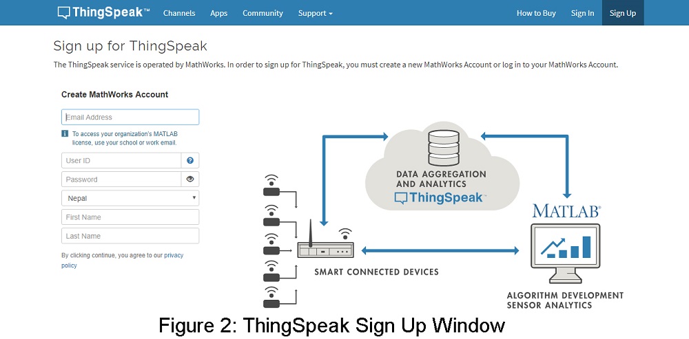
- Sign Up to ThingSpeak using your email ID and fill up the required field as shown in figure 2.
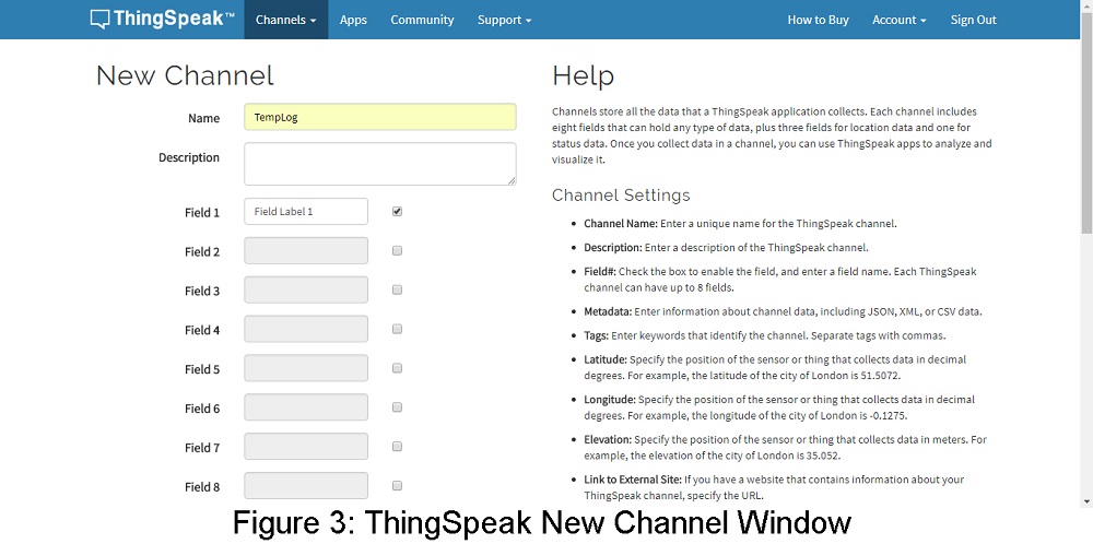
- Create a field as shown in fig.3 to create your channel and hit the save button.
- Now open your created channel and get your API key by clicking the API key tab you will get two API keys i.e. Write API key and Read API key as shown in figure 4.
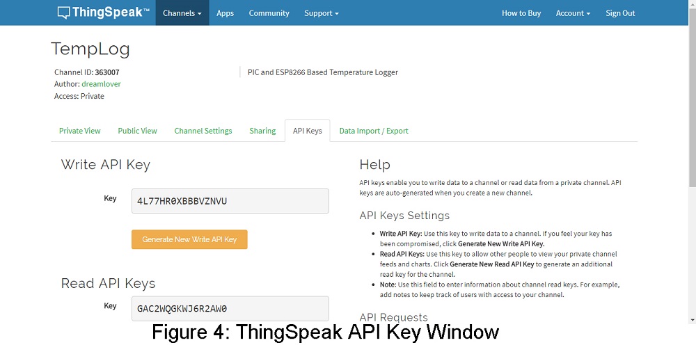
- Now you have three things; channel ID, a write API key, and a Read API key; use channel ID and write API key to use in C code and a read API key; to use in observing data on our cellphones or laptop. Store them carefully.
- Set the baud rate of the ESP8266 Wi-Fi module to 9600. Place a Wi-Fi modem that has an internet connection next to the setup.
- Open Temp-data-log. C source code and make the following changes: put your Wi-Fi name, Wi-Fi password, and API key in places of BEPWifi, BEP12345, and API key respectively in the previously listed code.
The Wi-Fi module ESP8266 performs tasks on basic AT commands. You can use the hyper terminal of the window to test ESP8266. The complete command of ESP8266 can be downloaded from the given link. www.pridopia.co.uk/pi-doc/ESP8266ATCommandsSet.pdf
To set the baud rate on the latest ESP8266 platform, use the AT+IPR command as AT+CIOBAUD no longer works in modern versions. Use the below link for a detailed view of the command. www.esp8266.com/viewtopic.php?f=13&t=718
To obtain the API keys, visit Data IMPORT/EXPORT section and open your channel. Alter the field value and provide the number you want to upload in this link https://api.thingspeak.com/update?api_key=4L77HR0XBBBVZNVU&field1=0
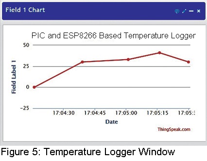
Then will find a graph of data of temperature details under the Private View Section similar to the one shown in fig. 5.
The link for cellphone and PC observation is provided in respective channels.
After the API key and channel id in that link are replaced by the reading of the API key and user’s channel ID, open that link on your device through browsers to get recorded graphic details of the temperature.
PARTS LIST OF ESP8266 TEMPERATURE LOGGER USING PIC16F887
| Resistors (all ¼-watt, ± 5% Carbon) |
| R1 = 1 KΩ
R2, R4, R5 = 10 KΩ R3 = 470 Ω VR1 = 10 KΩ Potmeter |
| Capacitors |
| C1 = 1000 µF, 35V (Electrolytic Capacitor)
C2, C3 = 0.1 µF (Ceramic Disc) C4 = 100 µF, 16V (Electrolytic Capacitor) C5, C6 = 10 µF, 16V (Electrolytic Capacitor) |
| Semiconductors |
| IC1 = 7805 (5V series voltage regulator)
IC2 = LM1117-3.3 (3.3V Linear Regulator) IC3 = LM35 (Temperature Sensor IC) IC4 = PIC16F887 (Microcontroller) Logic-Level-Shifter = 8-pin logic-level shifter WiFi Module = 8-pin ESP8266 Wi-Fi Module LCD1 = 16×2 Alphanumeric LED |
| Miscellaneous |
| SW1 – SW2 – Tactile Push-to-on Switch
CON1 = DC Adapter Connector |
How can I fix this error??
[HD44780] Controller received data whilst busy. [LCD1]
That might be due to most of the port B pin act ac analog.
First you have to convert all the to digital. For that add ADCON1=0b0111;
before lcdinit()
ADCON1=0b0111;
lcdinit();
[HD44780] Controller received data whilst busy. [LCD1]
Stil the same error. can you please correct this error and re upload the code or provide a new link. its very helpful thank you.
There is no issue in code.