The system “GPS Navigator Circuit using ATmega 16” is implemented to detect the position/location of anything under consideration, and hence it is suited for navigation activities.
Introduction to GPS Navigator Circuit using ATmega 16
The term GPS has been so popular in recent times. The credit for its quick recognition is due to the list of multiple features this system offers. Elaborated as a Global positioning system (GPS) it has already been established as a reliable technology that has made our lives much easier. Just with the involvement of GPS, we have observed a drastic change in the accuracy and efficiency of the project. Probably for the same reason, the mobile phone development team has incorporated an in-built GPS receiver, which is the reason why we can trace the location of the place we are standing at an instant. However, this instant location identification is possible when there is a distinct line-of-sight communication with four or more satellites.
Trusting GPS for the reasons listed above, we built a device called GPS Navigator Circuit using ATmega 16. With this device, the GPS signal from around the vicinity is collected, and then it is further processed to extract details about its current location. To extend the flexibility of the system, we did include a tracking record system. This feature will serve us best in two definite ways; one is to check on the path traveled so far which will ensure our safety, as we can always travel back to the point where we started in the case when we feel lost in the unknown locality.
Another project based on GPS posted on bestengineeringprojects.com
- GPS Module Interface with ATmega16
- DIY Distance Measurement using GPS and ATmega328P
- GPS and GSM based Vehicle Tracking System
- Accident Detection and Alert System using Arduino
Circuit and Working of GPS Navigator Circuit using ATmega 16
The complete circuit diagram of this device is given clearly in fig. 1. As we see the chief component of this project is a simple microcontroller called ATmega16 (IC1) around which the entire circuit is fabricated. Besides this, other components like 5V voltage regulator 7805 (IC2), GPS module, graphical LCD (GLCD1), and a few other components are included in this project.
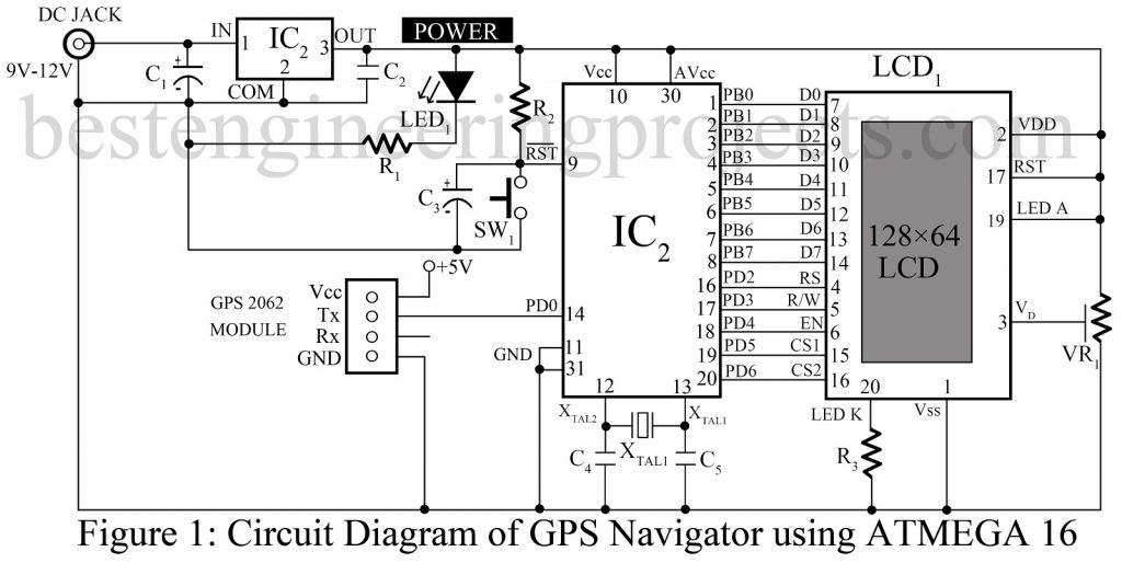
Talking about the supply, we have implemented a 9V/12V adaptor to power the circuit. The circuit consumes a regulated 5V supply from the regulator IC2 for efficient operation. When the circuit feeds on the power, LED1 glows to notify us about the power consumption scenario.
A clock frequency of 16 MHz is required to operate the microcontroller IC1. To establish a communication path between the GPS receiver modem and IC1, a serial protocol is used. The GPs receiver connects simultaneously and transfers data through Tx pin to the Rx (PD0) pin of IC1. The rate of data transfer is approximately 1 Hz.
Here we use a special type of LCD called GLCD to display the information collected. A normal LCD cannot display such enormous data, so a GLCD which is a 128×64-pixel and KS0108-controller-based device is used. To interface it with a microcontroller, port pins PB0-PB7 of IC1 are connected to data pins D0-D7 of GLCD1. Similarly, few pins from port D; PD2-PD6 are configured to provide control signals RS, R/W, EN, CS1, and CS2 to GLCD1, respectively. And, of course, we have Switch S1 to make necessary reset arrangements related to navigation.
Working of GPS Navigator Circuit using ATmega 16
Finally, let’s discuss how this navigating device works. When the adequate supply is offered to the circuit, first of all, the microcontroller is turned on and it quickly stores the initial values of longitude and latitude data marking the start point. And, as we move on with that device in hand, the varying values of longitudes and latitudes are continuously plotted in it forming the path we traveled; a clear picture for this explanation is given in fig.1.
To include a wide area on a small screen, we use certain rules of measurement such that 30 meters of distance traveled on the field is equivalent to 1 division change on the screen. Hence, after the recorded distances are plotted on the screen with respective latitude and longitude values, what we get is a distinct view of the path we traveled so far and the details about turns and directions we followed. Besides this, from the map developed, other information regarding the current latitude, longitude, speed, altitude, date, time, etc are known. In addition, the total number of satellites our GPS modem can capture can also be known.
Software for GPS Navigator Circuit using ATmega 16
The fact that the ‘C’ language is used in coding makes it easier to implement. For the compiling purpose, we use WINAVR Programmers Notepad. WINAVR is a GCC–based compiler for AVR. To burn the code into the microcontroller we can use any program burner/loader with FUSE BYTE settings mentioned below:
Lfuse-0xef
H fuse-0x99
The data is sent continuously by GPS receiver modem to IC1 through USART at a 9600 baud rate. The data sent by GPS is initiated by a ‘$’ sign which is further followed by National Marine Electronics Association (NMEA) output sentences. For additional details, refer to Table I.
On the other hand, the microcontroller is ready to continuously capture and store all bytes for each NMEA output sequence. Now, the total bytes are partitioned and distinctly sampled into a small packet that contains information about time, date, longitude, latitude, altitude, speed, etc. All such values are continuously monitored and updated on the GLCD screen.
Click Here to Download Software Code
Construction and testing of GPS Navigator Circuit using ATmega 16
The figure of the actual size of the single-side PCB layout for the GPS navigator circuit is illustrated in Fig. 2. The respective component layout is given in Fig. 3. Follow the pattern as in the circuit to assemble the components on the PCB and reduce possible errors during assembling. To protect IC1, use IC base. For the supply, we can implement a 9V/12V adaptor. It can also be replaced with any other suitable DC source.
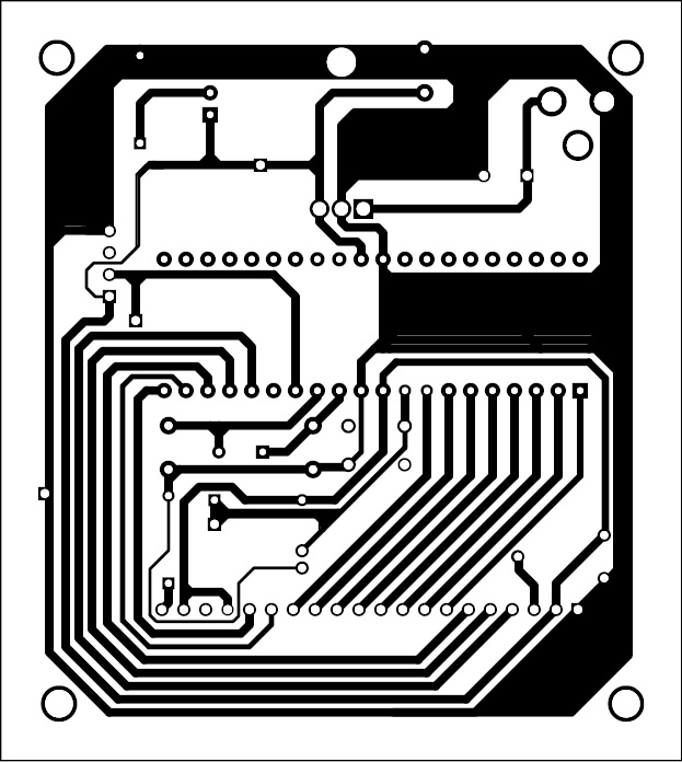
Figure 2: Solder Side PCB design of GPS Navigation Circuit Using ATmega 16
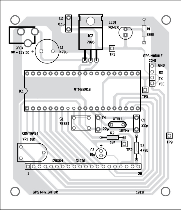
Figure 3: Component Side PCB design of GPS Navigation Circuit Using ATmega 16
For testing the entire circuit, make sure at Vcc of IC2 there is a 5V power supply concerning the GND pin. And, at the Tx pin of the GPS module, with the help of an oscilloscope, we can view the data transmitted by the GPS modem.
PARTS LIST OF GPS NAVIGATOR CIRCUIT USING ATMEGA 16
| Resistor (all ¼-watt, ± 5% Carbon) |
| R1 = 680 Ω
R2 = 10 KΩ R3 = 470 Ω VR1 = 10 KΩ |
| Capacitors |
| C1 = 470 µF, 25V (Electrolytic Capacitor)
C2 = 0.1 µF (Ceramic Disc) C3 = 10µF, 16V (Electrolytic Capacitor) C4, C4 = 22pF (Ceramic Disc) |
| Semiconductors |
| IC1 = 7805, 5V regulator
IC2 = ATmega 16 microcontroller LED1 = 5mm LED LCD1 = 2-pin 128*64 Graphic LCD (KS0108 Controller Based) |
| Miscellaneous |
| SW1 = Tactile Switch
XTAL1 = 16 MHz crystal oscillator GPS = GPS-2062 Module DC jack Connector |
Bonjour
j ai programmé l atmega 16 circuit de navigation GPS utilisant ATmega 16 mais je n ai aucunes images qui apparait sur l ecran doit je branche le module gps
Hi, Henri, sorry I did not understand the comment. Please ask questions in English.
Hello I programmed the atmega 16 GPS navigation circuit using ATmega 16 but I have no images that appear on the screen should I connect the gps module the quartz oscillates does it have 16mhz or do I have to connect the gps module so that it oscillates
i flashed the exe with ponyprog
no problem
I have no oscillation on the quartz
I plugged in the glcd the screen lights up that’s all
Thanks
Hi, you have to connect both GPS as well as crystal. The image on the LCD is the result of GPS data.
THANK YOU
Hello
I programmed the atmega 16 with ponyprog serial port also with usbasp configured the fuses correctly the program is installed correctly I see the frames of the neo6m but I have no quartz oscillation nor any images on the glcd I power the assembly with a 9v battery what software did you program the microcontroller with?
Thanks
Hi Henri, you have to use a crystal oscillator. For the compiling purpose, we use WINAVR Programmers and for burn, TL866II Plus is used.
hello
I also tried with xgpro it programs very well with a 16 mhz quartz but when I measure the quartz on the oscilloscope I have nothing
the atmega 16should oscillate at the frequency?
Thanks
Hello
the program is in exe bin must I send it directly like that or I must convert it with winavr thank you
You donot need to recompile, you can upload the HEX code to your controller.
Hello
I tried again to see what was wrong I think it is the display that is not compatible I am sending you the reference of the glcd can you tell me if it is compatible 12864 128×64 Dots Graphic LCD Module Display GLCD w/KS0107+KS0108 Controller I actually have lots of signals going to the pins of the display but I have the screen that lights up that’s all
can you give me the exact reference of the display
Thanks
can i use instead atmega16 atmega 32 ?
can i use instead gps module 2602 module NEO-6M?
Thanks