The DIY project Digital compass posted here utilizes an OLED display to show the direction (i.e. north). Another feature of this project is, it shows real data and time. DIY Digital Compass using ATmega8
A conventional compass utilizes a needle or a dial kept inside a compass rose. The conventional compass work on the principle of the earth’s magnetic field. But the projects DIY Digital Compass using ATmega8 posted here use the sun position to show the direction, unlike the magnetic field. Thus, this DIY Digital Compass is not affected by the earth’s magnetic field.
Circuit Diagram of DIY Digital Compass using ATmega8
The circuit diagram of DIY Digital Compass using ATmega8 is shown in figure 1, built around an 8-bit microcontroller (ATmega8), an OLED (Organic Light Emitting Diode) display, an RTC (Real Time Clock) IC DC1307, and a few other electronic components (resistor, diode, voltage regulator, etc.).
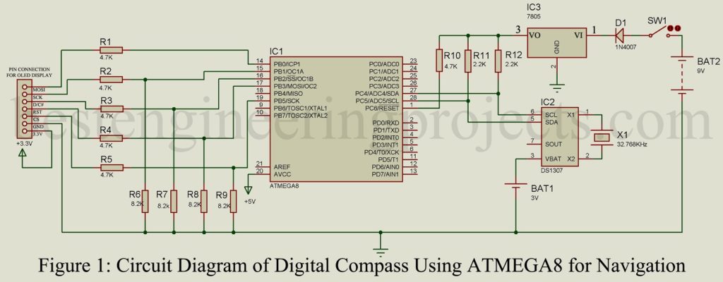
The circuit of DIY Digital Compass utilizes an RTC (Real Time Clock) IC DS1307 for indicating real date and time. If we talk about construction, DS1307 is a serial real-time cock IC with functions like calendar, 24-hour time format, or 12-hour time format with AM and PM indication. A crystal oscillator of 32.768KHz is connected to DS1307 as shown in figure 1, to provide the necessary clock pulse. The two lines SCL and SDA of DS1307 are connected to microcontroller pin PC4 and PC5 respectively for communication between them (read and write).
A button cell of 3V is connected to the VBAT pin of RTC IC (DS1307) to run the IC internally for a few days (approx. 10 days). The result of the RTC chip (date and time) is displayed in the OLED display.
The contrast ratio of this display is high (128×64) and is quite readable although the size of the screen is small (2.4 cm). Another reason to select OLED is, it consumes very low power because it does not require a backlight. Here in this project, we had to use the SSD1306 OLED display module which has an inbuilt driver chip thus it will be very easy to communicate with the microcontroller.
More other interesting projects using ATmega MCU posted in bestengineeringprojects.com
- ATmega8 Based Restaurant Menu Ordering System
- Interface 4×4 Keypad and ATmega32 with Single Pin
- VU Meter Circuit using ATmega32
- ATmega16 Based Voting Machine
- Ultrasonic Water Level Meter
Power Supply Circuit | DIY Digital Compass using ATmega8
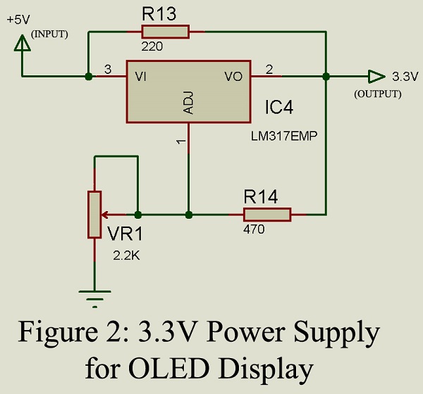
The project DIY Digital Compass utilize two levels of voltage i.e. 5V and 3.3V. The entire circuit except for the OLED display work on a 5V DC supply and OLED need 3.3V. The power supply of 9V is connected to the circuit which is further converted into a 5V power supply using a series voltage regulator IC 7805. 3.3V is converted using variable voltage regulator IC LM317 as shown in figure 2.
Software: The software of DIY Compass using ATmega8 is written in C programming language using Atmel studio 7.0 and burned in ATmega8 using MiniPro Programmer. You can directly download the software and use it without modifying but must change your longitude and latitude with your place in code. The code written for DIY Digital Compass is very simple and well commented so does not need any description.
Click Here to Download Software Code
PARTS LIST OF DIY DIGITAL COMPASS USING ATMEGA8
| Resistors (all ¼-watt, ± 5% Carbon) |
| R1 – R5, R10 = 4.7 KΩ
R6, R9 = 8.2 KΩ R11, R12 = 2.2 KΩ R13 = 220 Ω R14 = 470 Ω VR1 = 2.2 KΩ |
| Semiconductors |
| IC1 = ATmega8 (8-bit microcontroller)
IC2 = DS1307 (RTC IC) IC3 = 7805 (5V series voltage regulator) IC4 = LM317 D1 = 1N7007 (Genera rectifier diode) |
| Miscellaneous |
| OLED Display = SSD1306 (2.4CM display module)
X1 = 32.768KHz (crystal oscillator) BAT1 = 3V button cell BAT2 = 9V Battery |