A Volume Unit (VU) meter is a standard device that represents the signal level in audio equipment. This project “VU Meter Circuit using ATmega32” makes the representation process much easier since it avoids the use of any physical medium to establish the connection between the audio equipment or audio source and the circuit of the project. This way we can eliminate the hassle of using more components. It uses a bar graph LED for a visual representation of the audio.
ATmega32 is an 8-bit AVR (Alf and Vegard’s RISC processor, which isn’t an official acronym as per the developers yet it is ordinarily accepted as so) microcontroller with 40 pins among which 32 are I/O ports. These 32 ports are programmable and hence we can easily interface with other devices which makes ATmega32 ample to use in most embedded systems. Unlike the digital ICs, it is not a Plug and Play device. The programs must be written into the flash memory of Atmega32 using the ‘C’ programming language. ATmega8 and ATmega328p are some of the alternatives to ATmega32 microcontroller. Some of the common applications of the ATmeaga32 microcontroller are a coffee vending machine, temperature control systems, digital signal processing amongst the others.
Circuit and Working of VU Meter using ATmega32
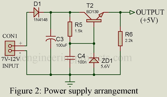
The overall diagram of the complete project is illustrated in figure 1and the illustration of the power supply arrangement is in figure 2. As shown in the circuit diagram, we can see that the heart of the project is IC1, which is an ATmega32A microcontroller. IC1 is surrounded by a few other components like a bar graph LED (BAR1), a 1N4148 diode (D1), two transistors: BC547 (T1) and BD139 (T2), etc.
A linear voltage regulator circuit is made up of transistor T2, two diodes: diode D1 and Zener diode ZD1 along with a few other passive components. A power supply of 7-12V, 200 mA sources required for the device to operate is fed through the connector CON1. The combination of a diode D1 and a capacitor C3 protects the circuit in reverse voltage connection and reduces the noise effects in the power supply respectively. The zener diode (ZD1) current is fixed by the resistor R5. The voltage at the end of the emitter terminal of the transistor T2 is found to be 4.9V.
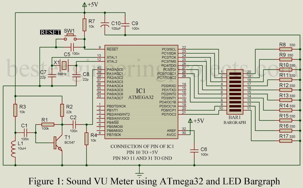
Another transistor T1 is employed to construct a preamplifier circuit. Two resistors; R1 and R2 are used to adjust the gain as feedback resistor and set the collector current respectively. Two coupling capacitors C1 and C2 are also used in the circuit.
This circuit captures the magnetic fields produced by the audio equipment when playing any music. Inductor L1(10µH) detects the magnetic field from the speaker and then passes to the preamplifier circuit for amplification. After that, the amplified output is transferred to the IC1 through analog-to-digital converter (ADC) pin 40. The reference voltage of the ADC is fixed at 2.5V and the pre-amplified output voltage is always less than 2Vpp.
Finally, the output from the microcontroller (IC1) drives the bar graph LED (BAR1) which is linked with the IC1 through Port C. The intensity of music can be determined from the number of LEDs glowing in the bar graph. The louder the music, the greater is the number of glowing LEDs.
Software Code for VU Meter Circuit using ATmega32
The project implements a simple program using the C programming language to develop the source code, which is compiled using Atmel Studio 6.2. A program burner STK500 does the work of loading the source code of the program into the microcontroller using a hex code.
CLICK HERE TO DOWNLOAD SOFTWARE CODE
PARTS LIST OF VU METER CIRCUIT WITHOUT USING MICROPHONE
| Resistors (all ¼-watt, ± 5% Carbon) |
| R1 = 100 KΩ
R2 = 22 KΩ R3, R4, R7 = 10 KΩ R5 = 1.5 KΩ R6 = 2.2 KΩ R8 – R17 = 330 Ω |
| Capacitors |
| C1, C2, C4 – C6, C9 = 100nF (Ceramic Disc)
C3 = 100 µF, 25V (Electrolytic Capacitor) C7, C8 = 22pF (Ceramic Disc) C10 = 100 µF, 16V (Electrolytic Capacitor) |
| Semiconductors |
| IC1 = ATmega32A (Microcontroller)
BAR1 =- 20-pin bargraph LED T1 = BC547 (general Purpose NPN Transistor) T2 = BD139 (NPN bi-polar Power Transistor) D1 = 1N4148 (Switching Signal Diode) ZD1 = 5.6V (Zener Diode) |
| Miscellaneous |
| CON1 = 2-pin terminal connector
X1 = 8MHz Crystal Oscillator SW1 = Push-to-on Switch L1 = 10 µH ferrite-core inductor Battery |
Various other Sound VU Meter posted in bestengineeringprjects.com are:
(This article was originally posted on Mar 7, 2018, and updated on May 16, 2021.)