The project ‘Arduino VU Meter’ uses 16×2 alphanumeric LCD to display signal level of audio. Basically, VU Meter is used to represent volume of audio equipment. Previously we had posted a project Sound VU Meter using Arduino which uses LEDs to represent the level of volume where audio is taken from microphone. Unlike sound VU meter using arduino the project Arduino VU meter take input audio from two different channels i.e. left channel and right channel.
Circuit Description of Arduino VU Meter
The circuit of Arduino VU Meter is shown in figure 1 build around Arduino Uno (MCU) and LCD. Basically, in hardware section we all have to know how to interface arduino and LCD. The data pin of LCD is connected to digital pin of arduino as shown in circuit diagram. The audio input is given to analog pin. Left channel audio is given to pin A2 and right channel audio is given to pin A4.
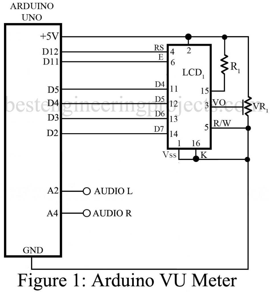
Resistor R1 is current limiting resistor connected to anode pin of LCD for backlight. Similarly, wiper of variable resistor is connected to pin 3 of LED in order to adjust the contrast of display.
Software: – The software code of arduino VU meter is written in arduino programming language and compiled and burned using arduino IDE.
You can directly download and use the code Click Here to Download
The program is straight forward except some special character. Here we had used some array of special character which is used to display height of bar of both rows.
|
1 2 3 4 5 6 7 8 9 10 11 12 13 14 15 16 17 18 19 20 21 22 23 24 25 26 27 28 29 30 31 32 33 34 35 36 37 38 39 40 41 42 43 44 45 46 47 48 49 50 51 52 53 54 |
byte p3[8] = { B10000, B10000, B10000, B10000, B10000, B10000, B10000, B10000 }; byte p4[8] = { B11000, B11000, B11000, B11000, B11000, B11000, B11000, B11000 }; byte p5[8] = { B11100, B11100, B11100, B11100, B11100, B11100, B11100, B11100 }; byte p6[8] = { B11110, B11110, B11110, B11110, B11110, B11110, B11110, B11110 }; byte p7[8] = { B11111, B11111, B11111, B11111, B11111, B11111, B11111, B11111 }; |
Similarly array L[8] and R[8] are used to display L and R in LCD.
|
1 2 3 4 5 6 7 8 9 10 11 12 13 14 15 16 17 18 19 20 21 |
byte L[8] = { B00000, B00000, B11111, B10000, B10000, B10000, B00000, B00000 }; byte R[8] = { B00000, B00000, B11111, B00101, B00101, B11010, B00000, B00000 }; |
Array K[8] and LEEG[8] combinedly display bar shape special character at the end of both rows a shown in figure 2.
|
1 2 3 4 5 6 7 8 9 10 11 12 13 14 15 16 17 18 19 20 21 |
byte K[8] = { B10101, B01010, B10101, B01010, B10101, B01010, B10101, B01010 }; byte LEEG[8] = { B00000, B00000, B00000, B00000, B00000, B00000, B00000, B00000 }; |
PARTS LIST OF ARDUINO VU METER
R1 = 470Ω
VR1 = 10 KΩ
Arduino Uno Board
16×2 Alphanumeric LCD